How to Use Red Pilot lamp: Examples, Pinouts, and Specs
Introduction
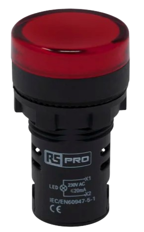
The Red Pilot Lamp is a small indicator light that emits red light, commonly used to signal power status or alert users to specific conditions in a circuit. It is a simple yet essential component in various electronic and electrical systems, providing a clear visual indication of operational states. Its compact size, low power consumption, and reliability make it a popular choice in control panels, machinery, appliances, and DIY electronics projects.
Explore Projects Built with Red Pilot lamp
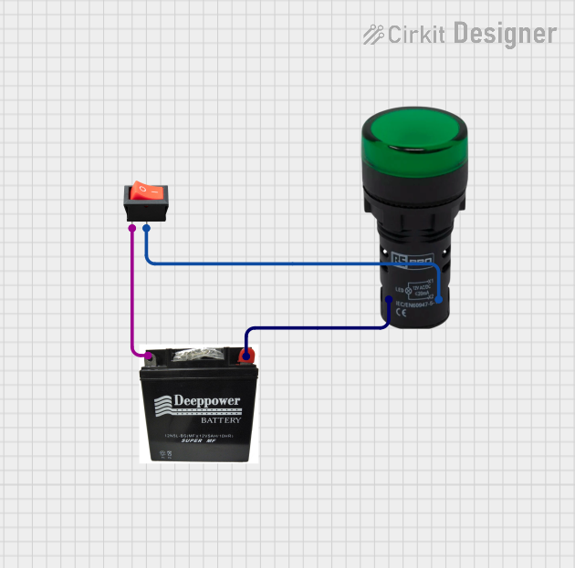
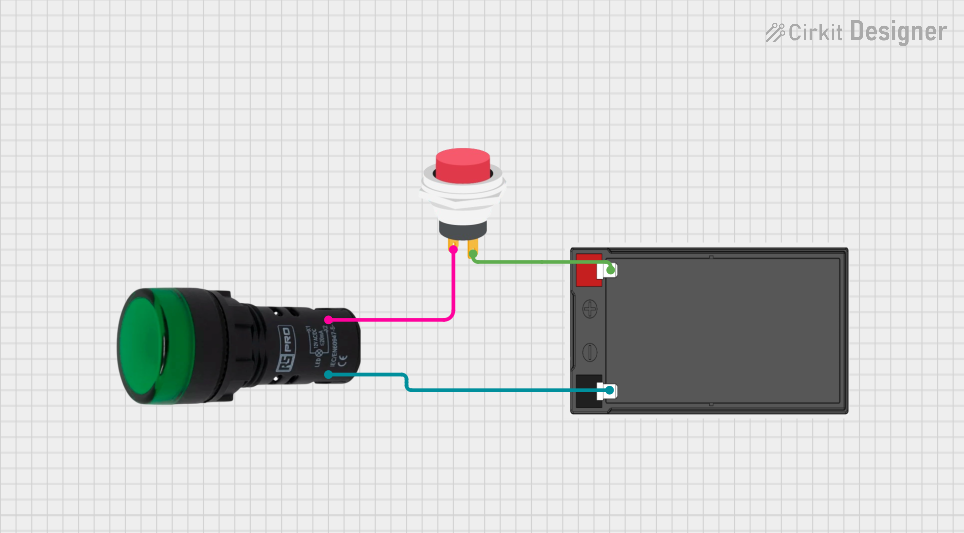
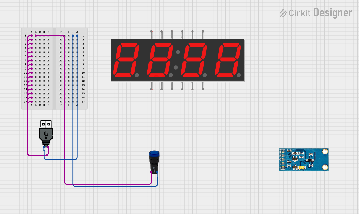
Explore Projects Built with Red Pilot lamp
Common Applications
- Power status indicators in control panels and appliances
- Warning or alert signals in industrial equipment
- Visual feedback in DIY electronics and Arduino projects
- Status indicators in automotive dashboards
Technical Specifications
Below are the key technical details of a typical Red Pilot Lamp:
| Parameter | Value |
|---|---|
| Operating Voltage | 6V, 12V, 24V, or 220V (varies by model) |
| Current Consumption | Typically 10-20 mA |
| Light Color | Red |
| Lamp Type | LED or incandescent |
| Mounting Style | Panel mount |
| Housing Material | Plastic or metal |
| Diameter | Common sizes: 8mm, 10mm, 12mm |
| Lifespan | Up to 50,000 hours (LED models) |
Pin Configuration and Descriptions
The Red Pilot Lamp typically has two terminals for connection:
| Pin | Description |
|---|---|
| Positive (+) | Connect to the positive terminal of the power supply. |
| Negative (-) | Connect to the negative terminal (ground). |
Usage Instructions
How to Use the Red Pilot Lamp in a Circuit
- Determine the Operating Voltage: Check the lamp's specifications to ensure it matches your circuit's voltage. For example, if the lamp is rated for 12V, use it in a 12V circuit.
- Connect the Terminals:
- Connect the positive terminal of the lamp to the positive side of the power supply.
- Connect the negative terminal to the ground or negative side of the power supply.
- Use a Resistor (if necessary): For LED-based pilot lamps, include a current-limiting resistor if the lamp does not have an internal resistor. Calculate the resistor value using Ohm's Law: [ R = \frac{V_{supply} - V_{lamp}}{I_{lamp}} ] Where ( V_{supply} ) is the supply voltage, ( V_{lamp} ) is the lamp's forward voltage, and ( I_{lamp} ) is the lamp's current.
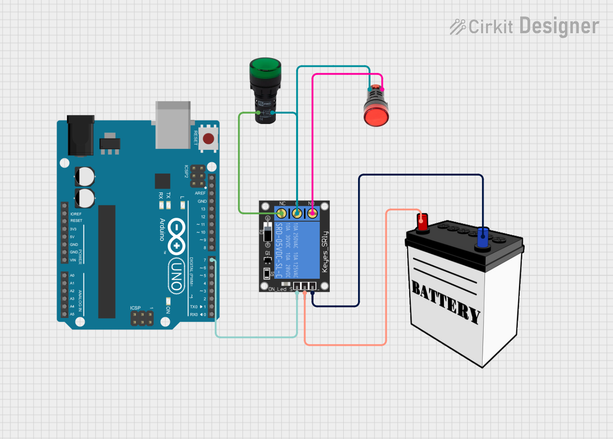
Example: Connecting to an Arduino UNO
The Red Pilot Lamp can be used as an indicator in Arduino projects. Below is an example of how to connect and control it:
Circuit Setup
- Connect the positive terminal of the lamp to a digital pin on the Arduino (e.g., pin 13) through a 220-ohm resistor.
- Connect the negative terminal of the lamp to the Arduino's GND pin.
Arduino Code
// Red Pilot Lamp Example with Arduino UNO
// This code turns the lamp ON for 1 second and OFF for 1 second repeatedly.

const int lampPin = 13; // Pin connected to the Red Pilot Lamp

void setup() {
  pinMode(lampPin, OUTPUT); // Set the lamp pin as an output
}

void loop() {
  digitalWrite(lampPin, HIGH); // Turn the lamp ON
  delay(1000);                 // Wait for 1 second
  digitalWrite(lampPin, LOW);  // Turn the lamp OFF
  delay(1000);                 // Wait for 1 second
}
Best Practices
- Ensure the operating voltage of the lamp matches the circuit voltage to avoid damage.
- Use appropriate resistors for LED-based lamps to prevent overcurrent.
- Securely mount the lamp in a panel or enclosure to protect it from mechanical stress.
Troubleshooting and FAQs
Common Issues and Solutions
| Issue | Possible Cause | Solution |
|---|---|---|
| Lamp does not light up | Incorrect wiring or loose connections | Verify connections and ensure proper polarity. |
| Lamp burns out quickly | Overvoltage or excessive current | Check the supply voltage and use a resistor. |
| Lamp flickers intermittently | Unstable power supply or loose connections | Stabilize the power source and secure wiring. |
| Lamp is too dim | Insufficient voltage or high resistance | Verify the supply voltage and resistor value. |
FAQs
Can I use the Red Pilot Lamp with AC power?
- Yes, but ensure the lamp is rated for AC operation. Some models are designed specifically for DC circuits.
What resistor value should I use for an LED-based lamp?
- Calculate the resistor value using the formula ( R = \frac{V_{supply} - V_{lamp}}{I_{lamp}} ). For example, with a 12V supply, a 2V lamp, and 20mA current, use a 500-ohm resistor.
Can I use the lamp without a resistor?
- Only if the lamp has an internal resistor. Otherwise, a resistor is necessary to limit current and prevent damage.
What is the typical lifespan of a Red Pilot Lamp?
- LED-based lamps can last up to 50,000 hours, while incandescent models have shorter lifespans.
By following this documentation, you can effectively integrate and troubleshoot the Red Pilot Lamp in your projects.