How to Use LCD 16S2H: Examples, Pinouts, and Specs
Introduction
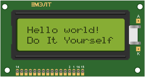
The LCD 16S2H (Manufacturer Part ID: MT-16S2H-2YLG) is a 16-character, 2-line liquid crystal display (LCD) module manufactured by Melt. It is designed for displaying alphanumeric characters and simple graphics, making it an essential component for a wide range of electronic projects. This module is widely used due to its simplicity, low power consumption, and compatibility with microcontrollers like Arduino.
Explore Projects Built with LCD 16S2H
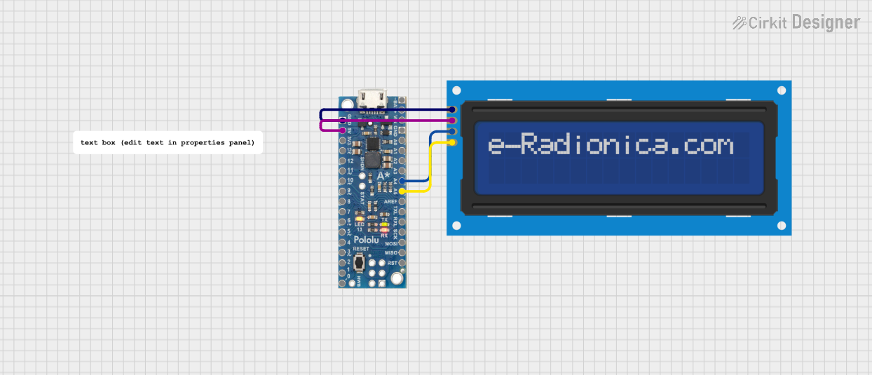

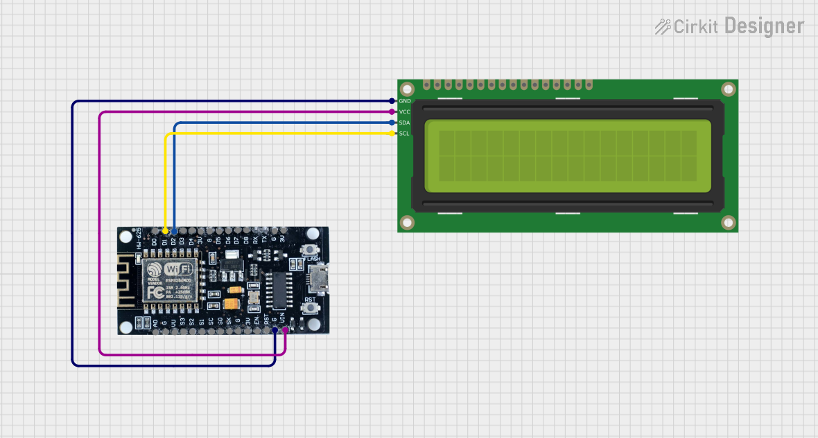
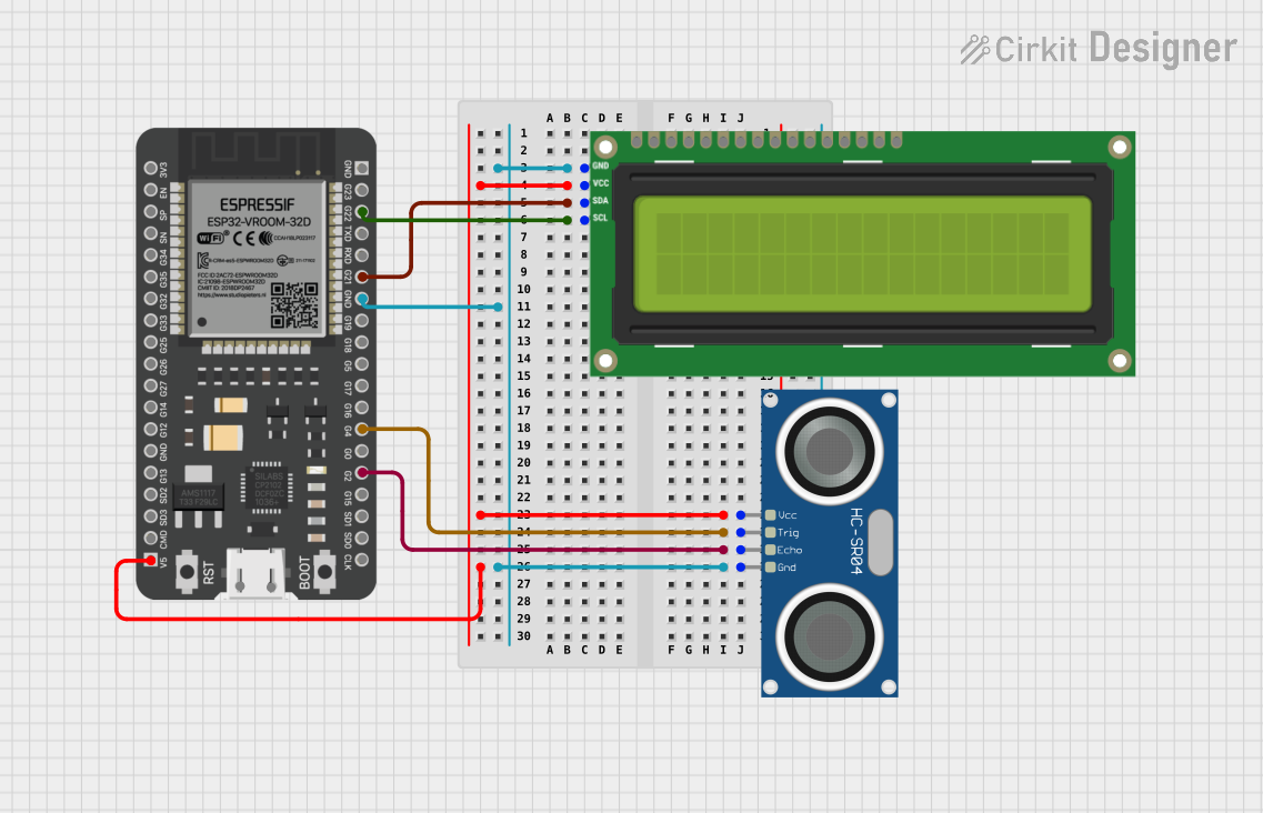
Explore Projects Built with LCD 16S2H
Common Applications
- Embedded systems and microcontroller projects
- Home automation displays
- Industrial control panels
- Educational and prototyping purposes
- Consumer electronics, such as clocks and calculators
Technical Specifications
The following table outlines the key technical details of the LCD 16S2H module:
| Parameter | Value |
|---|---|
| Manufacturer | Melt |
| Part ID | MT-16S2H-2YLG |
| Display Type | Alphanumeric LCD |
| Number of Characters | 16 characters x 2 lines |
| Operating Voltage | 4.7V to 5.3V |
| Operating Current | 1.5mA (typical) |
| Backlight Voltage | 4.2V to 4.6V |
| Backlight Current | 120mA (typical) |
| Character Size | 5.00mm x 8.00mm |
| Interface Type | Parallel (4-bit or 8-bit mode) |
| Operating Temperature | -20°C to +70°C |
| Storage Temperature | -30°C to +80°C |
Pin Configuration
The LCD 16S2H has a 16-pin interface. The table below describes each pin:
| Pin Number | Pin Name | Description |
|---|---|---|
| 1 | VSS | Ground (0V) |
| 2 | VDD | Power supply (+5V) |
| 3 | V0 | Contrast adjustment (connect to a potentiometer) |
| 4 | RS | Register Select (0: Command, 1: Data) |
| 5 | RW | Read/Write control (0: Write, 1: Read) |
| 6 | E | Enable signal (triggers data read/write) |
| 7 | D0 | Data bit 0 (used in 8-bit mode only) |
| 8 | D1 | Data bit 1 (used in 8-bit mode only) |
| 9 | D2 | Data bit 2 (used in 8-bit mode only) |
| 10 | D3 | Data bit 3 (used in 8-bit mode only) |
| 11 | D4 | Data bit 4 (used in both 4-bit and 8-bit modes) |
| 12 | D5 | Data bit 5 (used in both 4-bit and 8-bit modes) |
| 13 | D6 | Data bit 6 (used in both 4-bit and 8-bit modes) |
| 14 | D7 | Data bit 7 (used in both 4-bit and 8-bit modes) |
| 15 | LED+ | Backlight anode (connect to +5V through a current-limiting resistor) |
| 16 | LED- | Backlight cathode (connect to ground) |
Usage Instructions
Connecting the LCD 16S2H to an Arduino UNO
The LCD 16S2H can be easily interfaced with an Arduino UNO using the LiquidCrystal library. Below is a step-by-step guide:
Wiring the LCD:
- Connect the LCD pins to the Arduino as follows:
- VSS → GND
- VDD → 5V
- V0 → Middle pin of a 10kΩ potentiometer (other two pins to 5V and GND)
- RS → Digital Pin 12
- RW → GND
- E → Digital Pin 11
- D4 → Digital Pin 5
- D5 → Digital Pin 4
- D6 → Digital Pin 3
- D7 → Digital Pin 2
- LED+ → 5V (via a 220Ω resistor)
- LED- → GND
- Connect the LCD pins to the Arduino as follows:
Install the LiquidCrystal Library:
- The LiquidCrystal library is included with the Arduino IDE by default. No additional installation is required.
Upload the Code:
- Use the following example code to display text on the LCD:
#include <LiquidCrystal.h>

// Initialize the library with the pins connected to the LCD
LiquidCrystal lcd(12, 11, 5, 4, 3, 2);

void setup() {
  // Set up the LCD's number of columns and rows
  lcd.begin(16, 2);

  // Print a message to the LCD
  lcd.print("Hello, World!");
}

void loop() {
  // Move the cursor to the second line
  lcd.setCursor(0, 1);

  // Print a dynamic message
  lcd.print("Count: ");
  lcd.print(millis() / 1000); // Display elapsed time in seconds
}
Important Considerations
- Contrast Adjustment: Use a 10kΩ potentiometer to adjust the contrast of the display. Improper contrast settings may result in a blank or unreadable display.
- Backlight Resistor: Always use a current-limiting resistor (e.g., 220Ω) for the backlight to prevent damage.
- 4-bit vs. 8-bit Mode: For most applications, 4-bit mode is sufficient and reduces the number of required connections.
Troubleshooting and FAQs
Common Issues
Blank Screen:
- Cause: Incorrect contrast setting or power supply issue.
- Solution: Adjust the potentiometer connected to the V0 pin. Verify the power connections.
Flickering or Unstable Display:
- Cause: Poor connections or insufficient power supply.
- Solution: Check all connections and ensure a stable 5V power source.
Incorrect Characters Displayed:
- Cause: Data lines are not properly connected or configured.
- Solution: Verify the wiring and ensure the correct pins are defined in the code.
Backlight Not Working:
- Cause: Missing or incorrect resistor for the backlight.
- Solution: Add a 220Ω resistor between the LED+ pin and 5V.
FAQs
Q1: Can I use the LCD 16S2H with a 3.3V microcontroller?
A1: The LCD 16S2H is designed for 5V operation. To use it with a 3.3V microcontroller, you will need a level shifter or a 5V power source for the LCD.
Q2: How do I display custom characters?
A2: The LiquidCrystal library allows you to define custom characters using the createChar() function. Refer to the Arduino documentation for examples.
Q3: Can I use the LCD without a backlight?
A3: Yes, the LCD can function without a backlight, but visibility may be reduced in low-light conditions.
Q4: What is the maximum viewing angle of the LCD?
A4: The typical viewing angle is ±45° horizontally and ±30° vertically. For best results, view the display head-on.
By following this documentation, you can effectively integrate the LCD 16S2H into your projects and troubleshoot common issues with ease.