
How to Use Adafruit Feather M0 Adalogger: Examples, Pinouts, and Specs
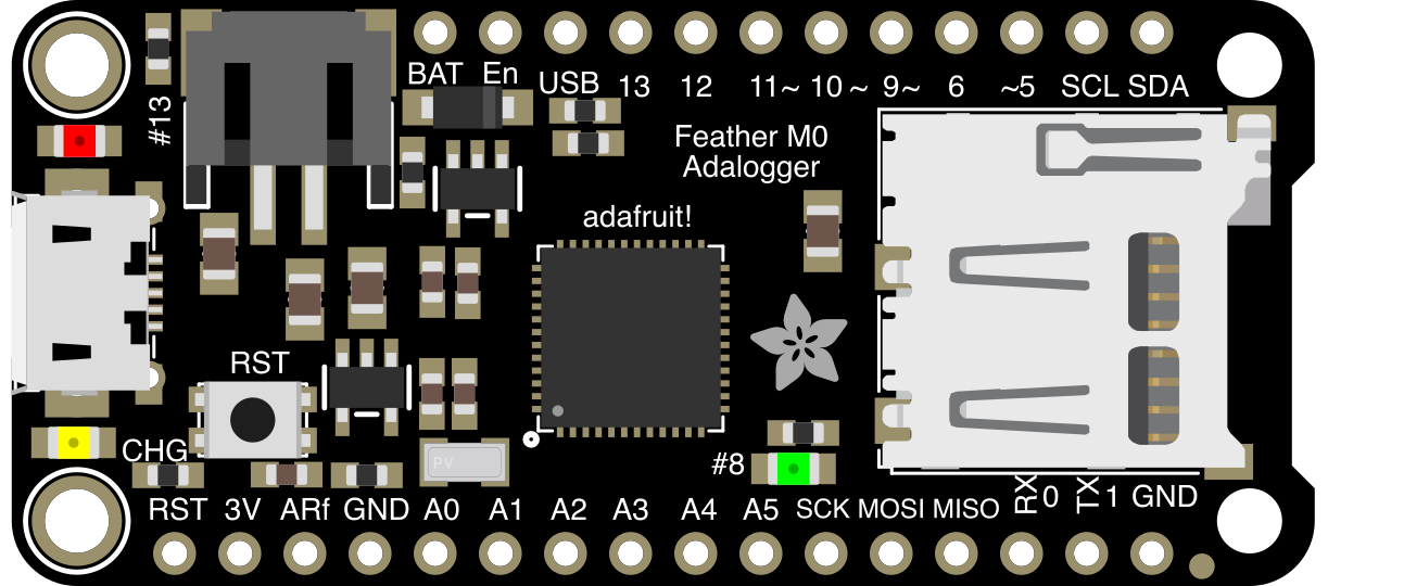
 Design with Adafruit Feather M0 Adalogger in Cirkit Designer
Introduction
The Adafruit Feather M0 Adalogger (Part ID: 2796) is a compact and versatile microcontroller board designed for low-power applications. It features an ARM Cortex-M0 processor and includes an onboard SD card slot for data logging, making it ideal for projects that require data storage and portability. The board is part of Adafruit's Feather ecosystem, which emphasizes small form factors and compatibility with a wide range of FeatherWing add-ons.
Explore Projects Built with Adafruit Feather M0 Adalogger
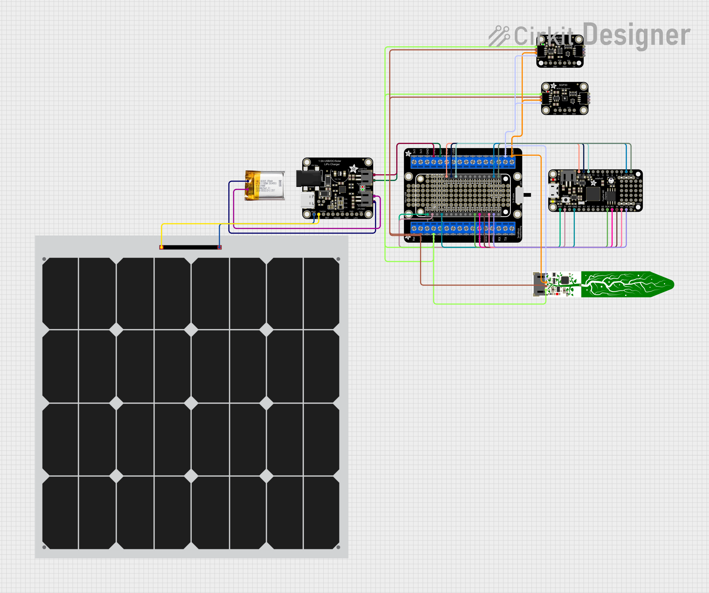 Open Project in Cirkit Designer
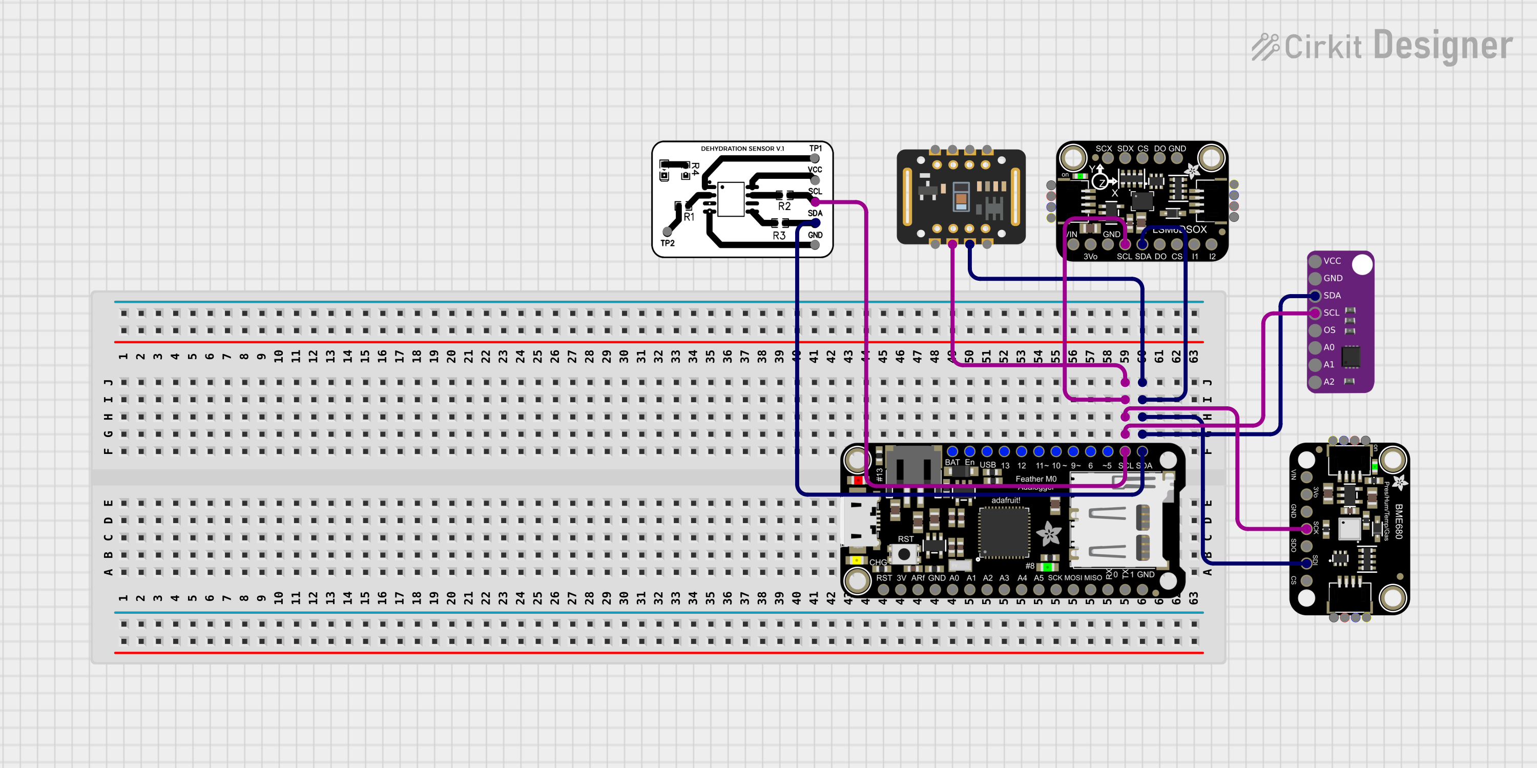 Open Project in Cirkit Designer
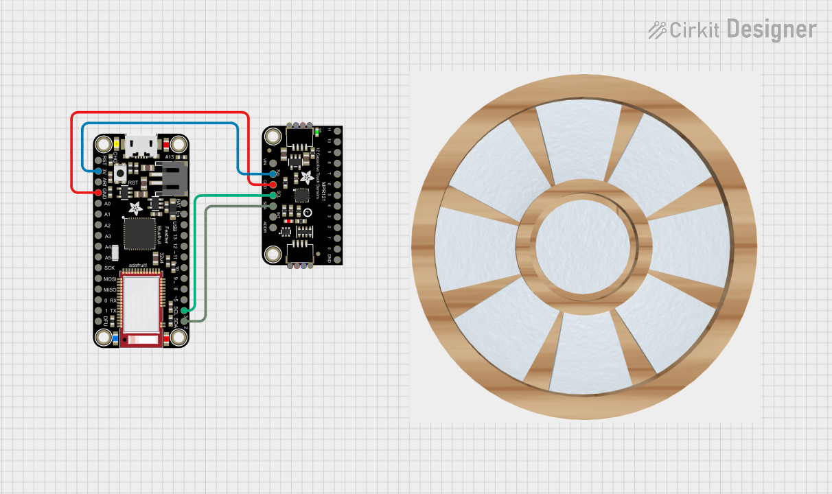 Open Project in Cirkit Designer
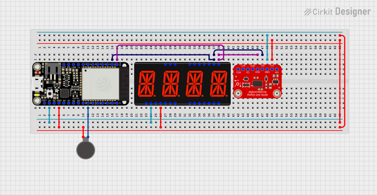 Open Project in Cirkit Designer
Explore Projects Built with Adafruit Feather M0 Adalogger
Open Project in Cirkit DesignerOpen Project in Cirkit DesignerOpen Project in Cirkit DesignerOpen Project in Cirkit DesignerCommon Applications and Use Cases
- Environmental data logging (e.g., temperature, humidity, pressure)
- IoT (Internet of Things) devices
- Portable and battery-powered projects
- Prototyping with sensors and actuators
- Educational projects and workshops
Technical Specifications
The Adafruit Feather M0 Adalogger is packed with features that make it suitable for a variety of applications. Below are its key technical details:
Key Technical Details
- Microcontroller: ATSAMD21G18 ARM Cortex-M0, 32-bit
- Operating Voltage: 3.3V
- Clock Speed: 48 MHz
- Flash Memory: 256 KB
- SRAM: 32 KB
- Power Supply: USB or LiPo battery (3.7V)
- SD Card Slot: Supports microSD cards for data logging
- Connectivity: Native USB support
- GPIO Pins: 20 (including analog and digital pins)
- Analog Inputs: 6 (12-bit ADC)
- PWM Outputs: 8
- I2C, SPI, UART: Supported
- Dimensions: 51mm x 23mm x 8mm
- Weight: 5.7g
Pin Configuration and Descriptions
The Adafruit Feather M0 Adalogger has a total of 20 GPIO pins, each with specific functions. Below is a detailed pinout:
| Pin | Label | Function |
|---|---|---|
| 1 | A0 - A5 | Analog inputs (12-bit ADC), can also be used as digital I/O |
| 2 | D0 - D13 | Digital I/O pins, some with PWM capability |
| 3 | SDA, SCL | I2C communication pins |
| 4 | MOSI, MISO, SCK | SPI communication pins |
| 5 | RX, TX | UART communication pins for serial data |
| 6 | 3V3, GND | Power pins (3.3V output and ground) |
| 7 | BAT | Battery voltage monitoring pin |
| 8 | EN | Enable pin to turn the board on/off |
| 9 | USB | USB power input and data communication |
| 10 | LIPO | LiPo battery connector for portable power |
Usage Instructions
The Adafruit Feather M0 Adalogger is easy to use and integrates seamlessly with the Arduino IDE. Below are the steps to get started and important considerations for using the board effectively.
How to Use the Component in a Circuit
Powering the Board:
- Connect the board to your computer via a micro-USB cable for power and programming.
- Alternatively, connect a 3.7V LiPo battery to the JST connector for portable operation.
Programming the Board:
- Install the Arduino IDE and add the Adafruit SAMD Boards package via the Board Manager.
- Select "Adafruit Feather M0" as the board type in the Arduino IDE.
- Write your code and upload it to the board using the USB connection.
Connecting Peripherals:
- Use the GPIO pins to connect sensors, actuators, or other peripherals.
- For data logging, insert a microSD card into the onboard SD card slot.
Data Logging Example:
- Below is an example Arduino sketch for logging temperature data to an SD card using a DHT22 sensor:
#include <SPI.h>
#include <SD.h>
#include <DHT.h>

// Define SD card chip select pin
#define SD_CS 4

// Define DHT sensor pin and type
#define DHTPIN 2
#define DHTTYPE DHT22

DHT dht(DHTPIN, DHTTYPE);
File dataFile;

void setup() {
  Serial.begin(9600);
  while (!Serial) {
    // Wait for Serial Monitor to open
  }

  // Initialize DHT sensor
  dht.begin();

  // Initialize SD card
  if (!SD.begin(SD_CS)) {
    Serial.println("SD card initialization failed!");
    return;
  }
  Serial.println("SD card initialized.");
}

void loop() {
  // Read temperature and humidity
  float temp = dht.readTemperature();
  float humidity = dht.readHumidity();

  // Check if readings are valid
  if (isnan(temp) || isnan(humidity)) {
    Serial.println("Failed to read from DHT sensor!");
    return;
  }

  // Open file for writing
  dataFile = SD.open("datalog.txt", FILE_WRITE);
  if (dataFile) {
    // Write data to file
    dataFile.print("Temperature: ");
    dataFile.print(temp);
    dataFile.print(" *C, Humidity: ");
    dataFile.print(humidity);
    dataFile.println(" %");
    dataFile.close(); // Close file
    Serial.println("Data logged.");
  } else {
    Serial.println("Error opening datalog.txt!");
  }

  delay(2000); // Wait 2 seconds before next reading
}
Important Considerations and Best Practices
- Power Supply: Ensure the board is powered with a stable 3.3V source. Avoid exceeding the voltage limits to prevent damage.
- SD Card Formatting: Format the microSD card to FAT16 or FAT32 before use.
- Battery Monitoring: Use the BAT pin to monitor the LiPo battery voltage for low-power applications.
- Pin Voltage Levels: The GPIO pins operate at 3.3V logic levels. Avoid connecting 5V signals directly to the pins.
Troubleshooting and FAQs
Common Issues and Solutions
Board Not Recognized by Arduino IDE:
- Ensure the correct board type ("Adafruit Feather M0") is selected in the IDE.
- Install the Adafruit SAMD Boards package via the Board Manager.
SD Card Initialization Fails:
- Check the SD card connection and ensure it is properly inserted.
- Verify that the SD card is formatted to FAT16 or FAT32.
Sensor Readings Are NaN:
- Ensure the sensor is connected to the correct pins and powered properly.
- Verify the sensor type and pin definitions in the code.
Board Not Powering On:
- Check the USB cable and port for proper connection.
- If using a battery, ensure it is charged and connected to the JST connector.
FAQs
Q: Can I use the Feather M0 Adalogger with 5V sensors?
A: The Feather M0 operates at 3.3V logic levels. Use a level shifter to interface with 5V sensors.
Q: What is the maximum SD card size supported?
A: The board supports microSD cards up to 32GB formatted in FAT16 or FAT32.
Q: Can I use the board without a battery?
A: Yes, the board can be powered via USB without a battery. However, a battery is required for portable applications.
Q: How do I reset the board?
A: Press the reset button on the board to restart the microcontroller.
This concludes the documentation for the Adafruit Feather M0 Adalogger. For additional support, visit the Adafruit Learning System.