How to Use AC Dimmer 4 channels: Examples, Pinouts, and Specs
Introduction
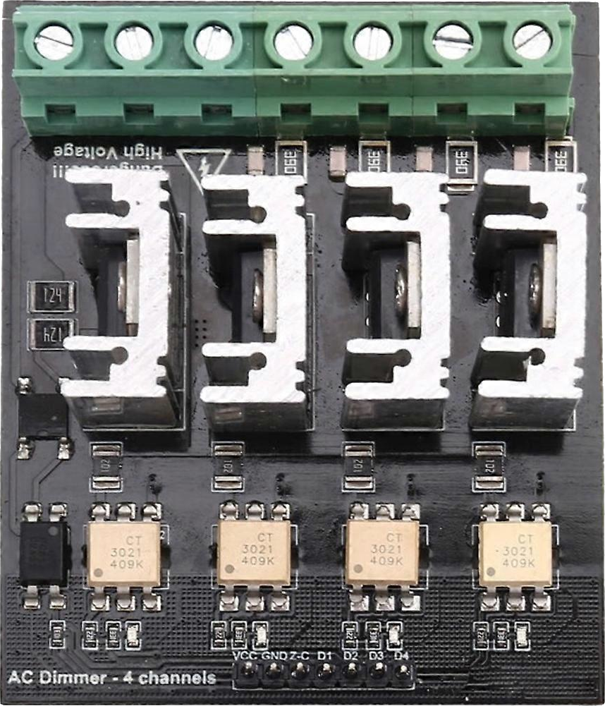
The AC Dimmer 4 Channels is an electronic device designed to control the brightness of lights by adjusting the voltage and current supplied to the light fixtures. This component allows for independent control of up to four separate channels, making it ideal for applications requiring multi-zone lighting control. It is commonly used in home automation, stage lighting, and industrial lighting systems.
Explore Projects Built with AC Dimmer 4 channels
Explore Projects Built with AC Dimmer 4 channels
Common Applications and Use Cases
- Smart home lighting systems
- Theater and stage lighting
- Industrial lighting control
- Decorative lighting setups
- Energy-saving lighting solutions
Technical Specifications
The AC Dimmer 4 Channels is designed to work with a variety of AC loads, including incandescent bulbs, dimmable LED lights, and other resistive or inductive loads. Below are the key technical details:
| Parameter | Value |
|---|---|
| Input Voltage | 110V - 240V AC |
| Output Channels | 4 |
| Maximum Load per Channel | 2A (440W at 220V, 220W at 110V) |
| Total Maximum Load | 8A |
| Control Signal | PWM (Pulse Width Modulation) |
| Control Voltage | 3.3V - 5V (compatible with microcontrollers) |
| Isolation | Opto-isolated control inputs |
| Operating Temperature | -10°C to 50°C |
| Dimensions | Varies by manufacturer (e.g., 100mm x 80mm x 25mm) |
Pin Configuration and Descriptions
The AC Dimmer 4 Channels typically has the following pin configuration:
Control Input Pins
| Pin Name | Description |
|---|---|
| CH1 | PWM input for Channel 1 |
| CH2 | PWM input for Channel 2 |
| CH3 | PWM input for Channel 3 |
| CH4 | PWM input for Channel 4 |
| GND | Ground connection for control signals |
| VCC | Power supply for control circuit (3.3V - 5V) |
AC Power and Load Connections
| Pin Name | Description |
|---|---|
| AC_L | Live wire input from AC mains |
| AC_N | Neutral wire input from AC mains |
| OUT1 | Output for Channel 1 |
| OUT2 | Output for Channel 2 |
| OUT3 | Output for Channel 3 |
| OUT4 | Output for Channel 4 |
Usage Instructions
How to Use the Component in a Circuit
Connect the AC Input:
- Connect the live (L) and neutral (N) wires from the AC mains to the
AC_LandAC_Nterminals of the dimmer module.
- Connect the live (L) and neutral (N) wires from the AC mains to the
Connect the Loads:
- Attach the light fixtures or other AC loads to the output terminals (
OUT1,OUT2,OUT3,OUT4) corresponding to the channels you wish to control.
- Attach the light fixtures or other AC loads to the output terminals (
Connect the Control Signals:
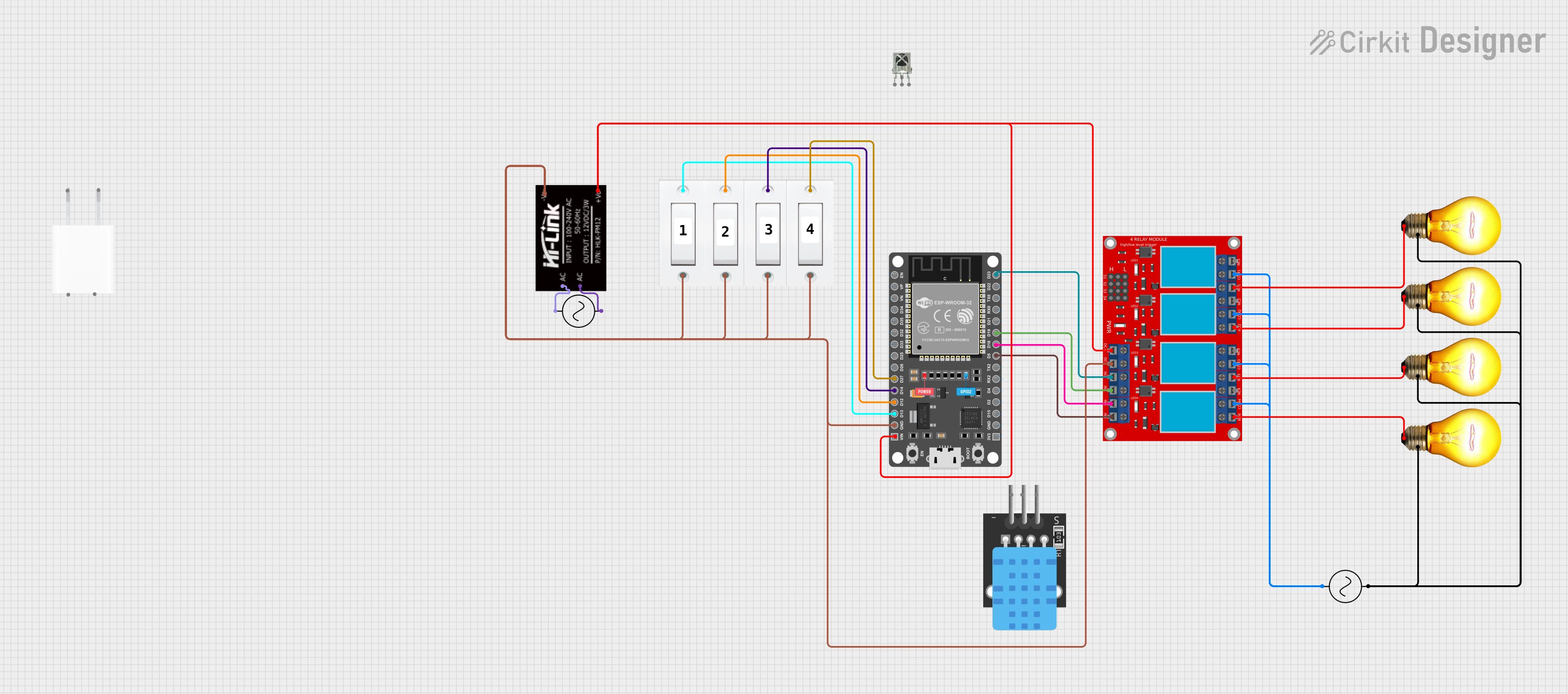
- Use a microcontroller (e.g., Arduino UNO) to generate PWM signals for each channel.
- Connect the PWM output pins of the microcontroller to the control input pins (
CH1,CH2,CH3,CH4) of the dimmer module. - Ensure the
GNDof the microcontroller is connected to theGNDof the dimmer module.
Power the Control Circuit:
- Supply 3.3V or 5V to the
VCCpin of the dimmer module.
- Supply 3.3V or 5V to the
Test the Setup:
- Gradually adjust the PWM duty cycle to control the brightness of the connected lights.
Important Considerations and Best Practices
- Safety First: Always ensure the AC mains power is disconnected before wiring the dimmer module.
- Load Compatibility: Verify that the connected loads are dimmable and do not exceed the maximum load rating per channel.
- Isolation: The control inputs are opto-isolated for safety, but additional isolation (e.g., using relays) may be required in high-risk environments.
- PWM Frequency: Use a PWM frequency between 50Hz and 120Hz for optimal dimming performance.
- Heat Dissipation: Ensure adequate ventilation or heat sinks to prevent overheating during operation.
Example Code for Arduino UNO
Below is an example code snippet to control the AC Dimmer 4 Channels using an Arduino UNO:
// Example code to control AC Dimmer 4 Channels with Arduino UNO
// Ensure the PWM pins used are compatible with analogWrite() function

#define CH1_PIN 3  // PWM pin for Channel 1
#define CH2_PIN 5  // PWM pin for Channel 2
#define CH3_PIN 6  // PWM pin for Channel 3
#define CH4_PIN 9  // PWM pin for Channel 4

void setup() {
  // Set PWM pins as output
  pinMode(CH1_PIN, OUTPUT);
  pinMode(CH2_PIN, OUTPUT);
  pinMode(CH3_PIN, OUTPUT);
  pinMode(CH4_PIN, OUTPUT);
}

void loop() {
  // Example: Gradually increase brightness on all channels
  for (int brightness = 0; brightness <= 255; brightness++) {
    analogWrite(CH1_PIN, brightness); // Adjust brightness for Channel 1
    analogWrite(CH2_PIN, brightness); // Adjust brightness for Channel 2
    analogWrite(CH3_PIN, brightness); // Adjust brightness for Channel 3
    analogWrite(CH4_PIN, brightness); // Adjust brightness for Channel 4
    delay(10); // Small delay for smooth dimming
  }

  // Example: Gradually decrease brightness on all channels
  for (int brightness = 255; brightness >= 0; brightness--) {
    analogWrite(CH1_PIN, brightness);
    analogWrite(CH2_PIN, brightness);
    analogWrite(CH3_PIN, brightness);
    analogWrite(CH4_PIN, brightness);
    delay(10);
  }
}
Troubleshooting and FAQs
Common Issues and Solutions
Lights Flicker or Do Not Dim Smoothly:
- Ensure the PWM frequency is within the recommended range (50Hz - 120Hz).
- Verify that the connected lights are dimmable and compatible with the dimmer module.
No Response from the Dimmer:
- Check all wiring connections, especially the control signal and AC input connections.
- Ensure the microcontroller is supplying the correct PWM signals.
Overheating:
- Verify that the total load does not exceed the maximum rating of the dimmer module.
- Provide adequate ventilation or use a heat sink to dissipate heat.
Microcontroller Not Controlling the Dimmer:
- Confirm that the
GNDof the microcontroller is connected to theGNDof the dimmer module. - Ensure the control voltage (3.3V or 5V) matches the dimmer module's requirements.
- Confirm that the
FAQs
Q: Can I use this dimmer with non-dimmable LED lights?
A: No, the dimmer is designed for use with dimmable lights only. Non-dimmable lights may flicker or get damaged.
Q: What happens if I exceed the maximum load per channel?
A: Exceeding the load rating can cause overheating, damage to the dimmer module, or even fire hazards. Always stay within the specified limits.
Q: Can I control the dimmer with a Raspberry Pi?
A: Yes, the dimmer can be controlled with a Raspberry Pi, but you may need to use a library or additional circuitry to generate appropriate PWM signals.
Q: Is the dimmer module safe to use with high-power appliances?
A: The dimmer is designed for lighting control and may not be suitable for high-power appliances. Always check the load specifications before use.