How to Use Adafruit Charlieplex 9x16 Blue: Examples, Pinouts, and Specs
Introduction
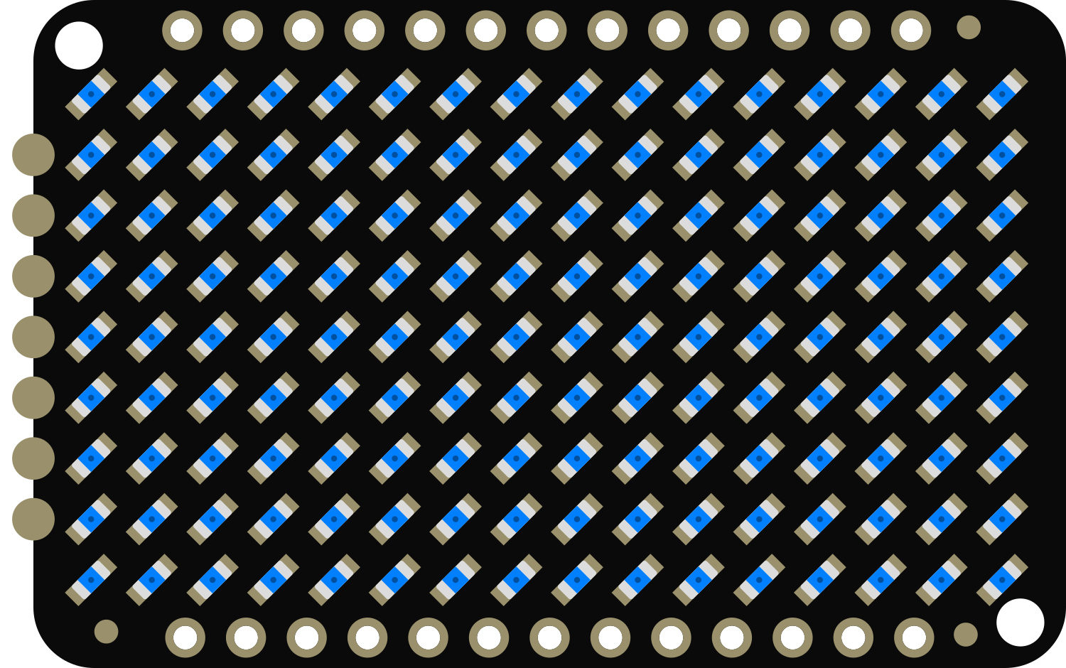
The Adafruit Charlieplex 9x16 Blue is a versatile and compact LED matrix that allows for the control of up to 144 blue LEDs with minimal pin usage. This is achieved through the charlieplexing technique, which is an efficient method for controlling multiple LEDs with fewer I/O pins. The matrix is ideal for creating eye-catching visual displays, wearable electronics, and informational signage.
Explore Projects Built with Adafruit Charlieplex 9x16 Blue

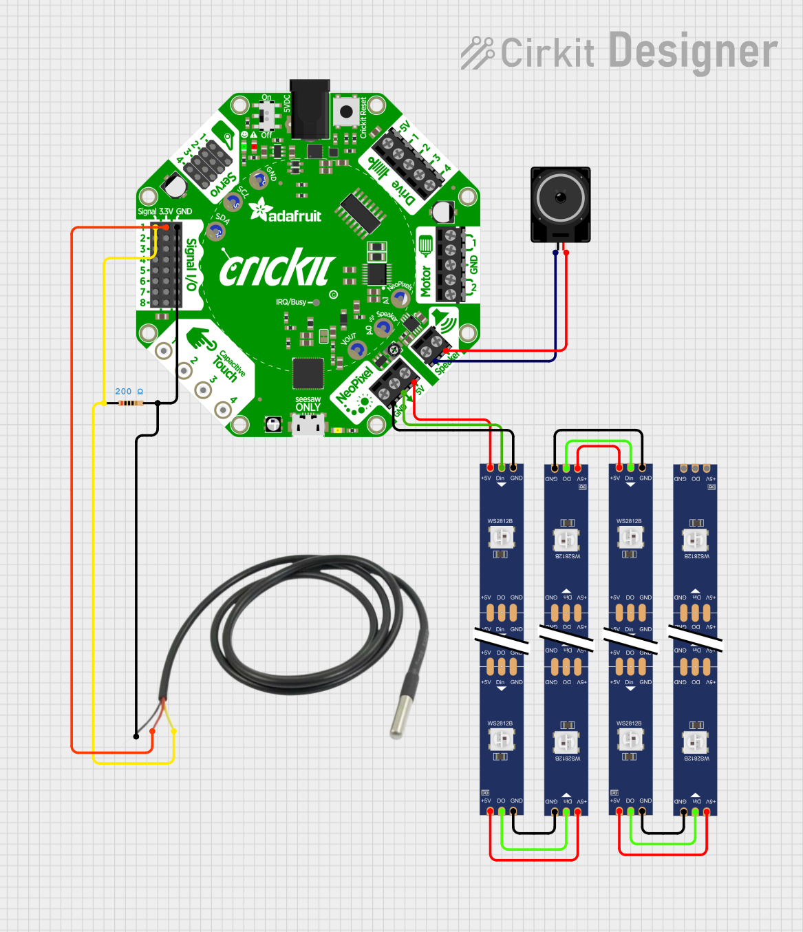
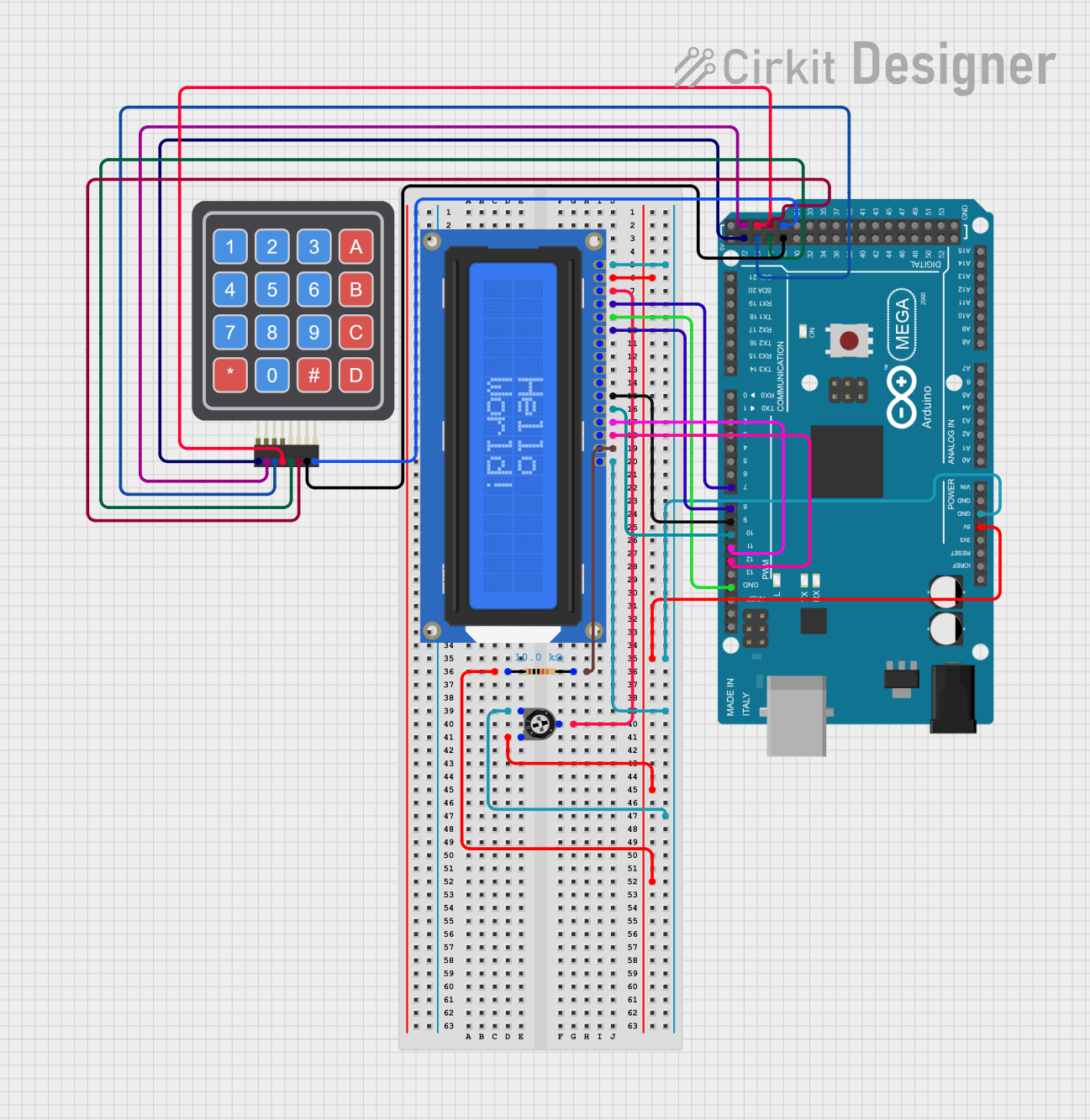

Explore Projects Built with Adafruit Charlieplex 9x16 Blue
Common Applications and Use Cases
- Wearable electronics
- Small-scale information displays
- Decorative lighting
- Prototyping for larger LED projects
- Educational tools for learning about charlieplexing and LED matrices
Technical Specifications
Key Technical Details
- LED Color: Blue
- Matrix Size: 9x16 LEDs
- Total LEDs: 144
- Operating Voltage: 3.0V - 5.5V
- Max Current per LED: 20mA
- Communication: I2C interface
Pin Configuration and Descriptions
| Pin Number | Name | Description |
|---|---|---|
| 1 | GND | Ground pin, common reference for the circuit |
| 2 | VCC | Power supply pin (3.0V - 5.5V) |
| 3 | SDA | I2C Data pin, used for sending data to the matrix |
| 4 | SCL | I2C Clock pin, used for clocking I2C data |
Usage Instructions
How to Use the Component in a Circuit
- Power Connections: Connect the VCC pin to the power supply (3.0V - 5.5V) and the GND pin to the ground of your power source.
- Data Connections: Connect the SDA and SCL pins to the corresponding I2C data and clock lines on your microcontroller (e.g., Arduino UNO).
- Addressing LEDs: Each LED can be addressed individually through the I2C interface using the provided library by Adafruit.
Important Considerations and Best Practices
- Ensure that the power supply voltage does not exceed the maximum rating of 5.5V to prevent damage to the LEDs.
- Limit the current through each LED to a maximum of 20mA.
- Use pull-up resistors on the I2C data lines if your microcontroller does not have built-in pull-ups.
- Avoid writing to the display too rapidly to prevent flickering.
- When designing enclosures or mounts, ensure adequate ventilation to prevent overheating.
Example Code for Arduino UNO
#include <Wire.h>
#include <Adafruit_IS31FL3731.h>

// Create the LED driver object
Adafruit_IS31FL3731 ledMatrix = Adafruit_IS31FL3731();

void setup() {
  Wire.begin(); // Initialize I2C
  if (!ledMatrix.begin()) {
    Serial.println("IS31FL3731 not found");
    while (1);
  }
  Serial.println("IS31FL3731 found!");
}

void loop() {
  // Clear the frame buffer
  ledMatrix.clear();

  // Draw a simple pattern
  for (int i = 0; i < 9; i++) {
    for (int j = 0; j < 16; j++) {
      ledMatrix.drawPixel(i, j, (i + j) % 2 ? 255 : 0);
    }
  }

  // Display the frame buffer on the LEDs
  ledMatrix.displayFrame();

  delay(500); // Wait for half a second
}
Note: This example assumes the use of the Adafruit IS31FL3731 library, which can be installed through the Arduino Library Manager.
Troubleshooting and FAQs
Common Issues
- LEDs Not Lighting Up: Ensure that the power supply is correctly connected and within the specified voltage range. Check the I2C connections and verify that the correct I2C address is being used.
- Flickering LEDs: This may be due to rapid updates to the display. Introduce a delay between updates or optimize the refresh rate.
- Partial Display Issues: If only part of the matrix is working, check for any cold solder joints or damaged LEDs.
Solutions and Tips for Troubleshooting
- Double-check all connections, especially the I2C lines, for proper contact and continuity.
- Use the
Serial.println()function to debug and verify that the microcontroller is communicating with the LED matrix. - Consult the Adafruit IS31FL3731 library documentation for additional functions and advanced usage.
FAQs
Q: Can I daisy-chain multiple Charlieplex matrices? A: Yes, multiple matrices can be daisy-chained using the I2C interface, but each matrix must have a unique I2C address.
Q: How do I set a unique I2C address for each matrix? A: The I2C address can be set by soldering the address jumpers on the back of the matrix. Refer to the Adafruit guide for the specific address configurations.
Q: What is the maximum brightness for the LEDs? A: The maximum brightness is determined by the current limit, which should not exceed 20mA per LED. Adjust the brightness within this limit to prevent damage.
Q: Can I use this matrix with a Raspberry Pi or other microcontrollers? A: Yes, the matrix can be used with any microcontroller that supports I2C communication, including the Raspberry Pi. Ensure that the appropriate library or code is used for the platform.
For further assistance, visit the Adafruit support forums or contact technical support.