How to Use IR LED: Examples, Pinouts, and Specs

Introduction
An Infrared Light-Emitting Diode (IR LED) is a specialized type of LED that emits light in the infrared spectrum, which is invisible to the human eye. IR LEDs are widely used in applications such as remote controls, proximity sensors, optical communication devices, and security systems. They are valued for their efficiency, low power consumption, and ability to transmit data wirelessly over short distances.
Common applications of IR LEDs include:
- Remote controls for TVs, air conditioners, and other appliances
- Infrared communication systems
- Proximity and obstacle detection in robotics
- Night vision and surveillance systems
- Optical encoders and data transmission
Explore Projects Built with IR LED
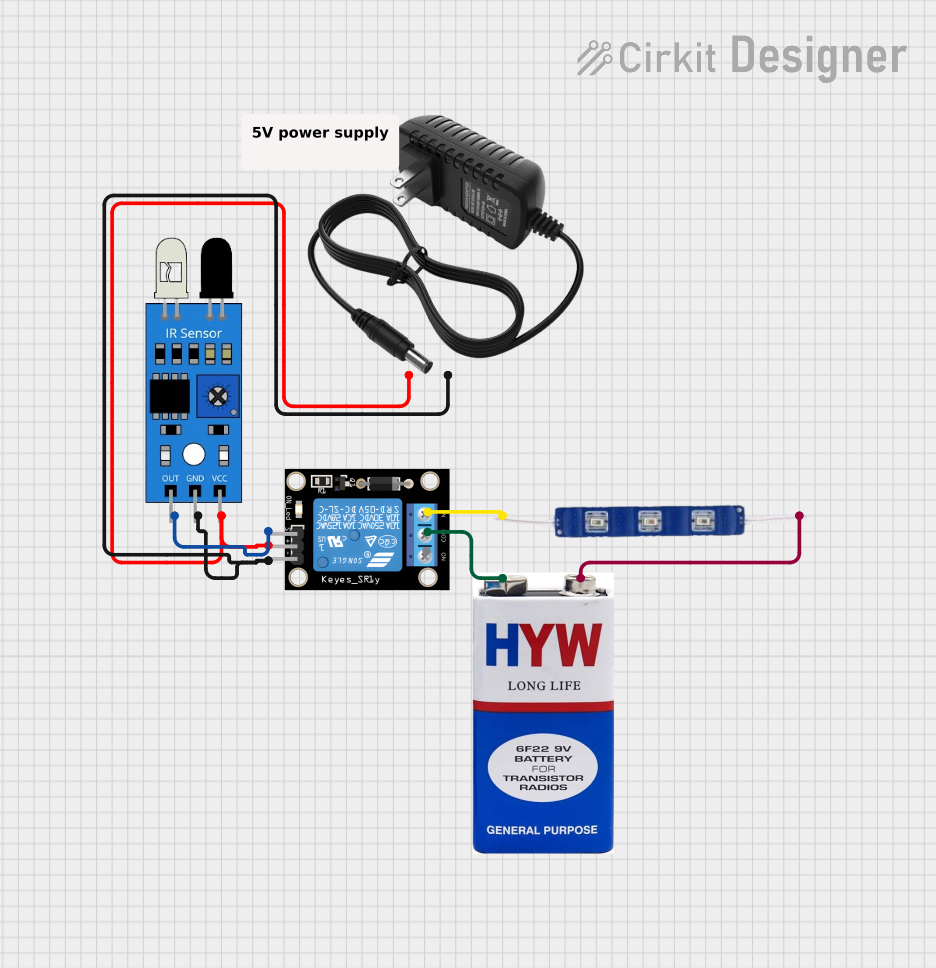
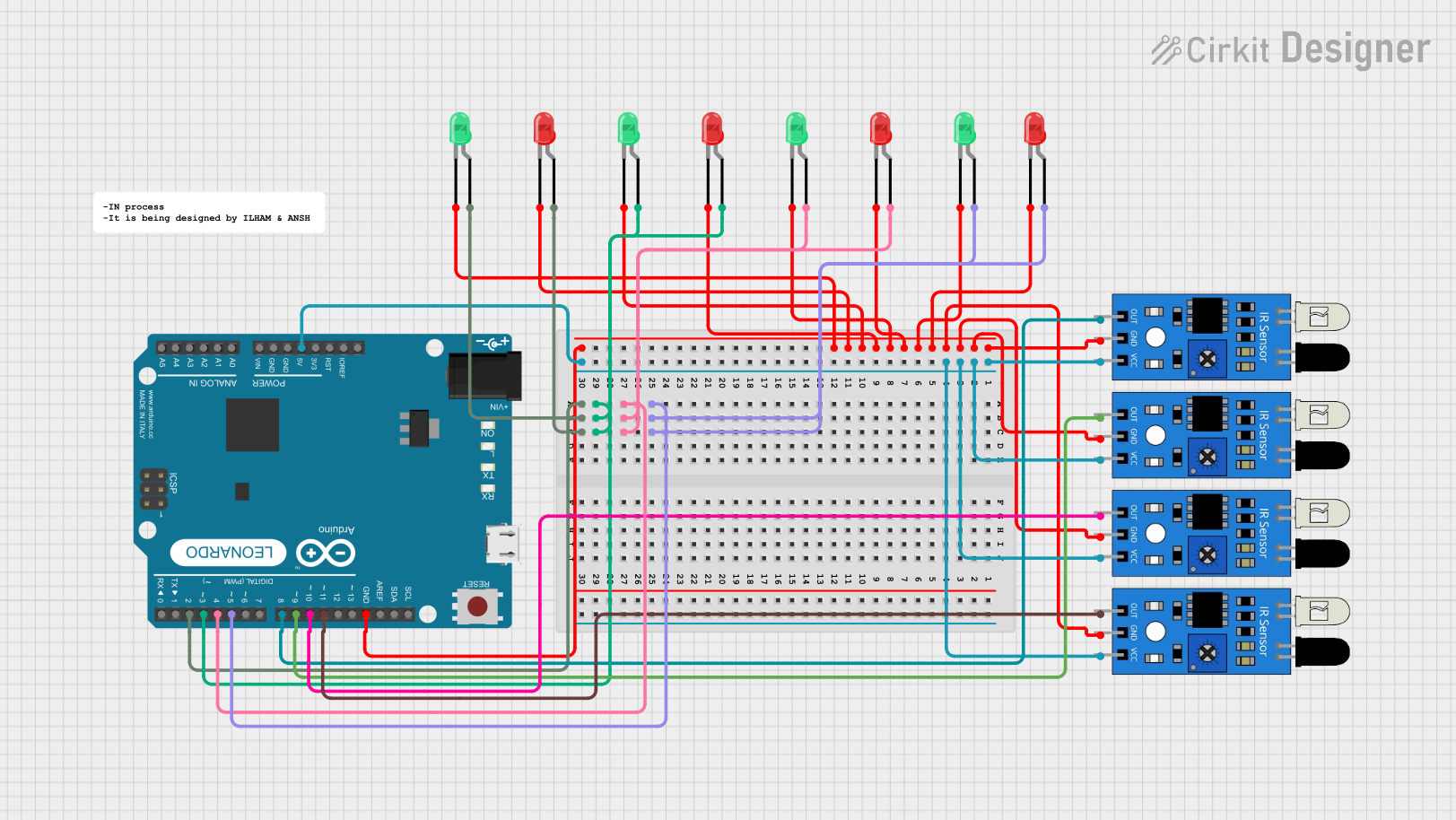
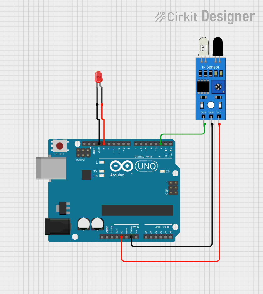
Explore Projects Built with IR LED
Technical Specifications
Below are the key technical details of a typical IR LED. Note that specific values may vary depending on the manufacturer and model.
| Parameter | Value |
|---|---|
| Wavelength | 850 nm to 950 nm |
| Forward Voltage (Vf) | 1.2V to 1.6V |
| Forward Current (If) | 20 mA (typical), 50 mA (max) |
| Power Dissipation | 100 mW (max) |
| Viewing Angle | 20° to 60° |
| Peak Emission Wavelength | 940 nm (typical) |
Pin Configuration
IR LEDs typically have two pins: the anode (positive) and the cathode (negative). The longer pin is the anode, and the shorter pin is the cathode. If the pins are of equal length, the flat edge on the LED casing indicates the cathode.
| Pin Name | Description |
|---|---|
| Anode | Connects to the positive terminal of the power supply or circuit. |
| Cathode | Connects to the negative terminal or ground. |
Usage Instructions
How to Use an IR LED in a Circuit
Determine the Resistor Value: To prevent damage to the IR LED, use a current-limiting resistor. Calculate the resistor value using Ohm's Law: [ R = \frac{V_{supply} - V_f}{I_f} ] Where:
- (V_{supply}) is the supply voltage
- (V_f) is the forward voltage of the IR LED
- (I_f) is the desired forward current (e.g., 20 mA)
Connect the IR LED:
- Connect the anode to the positive terminal of the power supply through the resistor.
- Connect the cathode to the ground.
Test the Circuit: Use a digital camera or smartphone camera to verify the IR LED is emitting light, as the human eye cannot see infrared light.
Important Considerations
- Polarity: Ensure correct polarity when connecting the IR LED. Reversing the polarity may damage the component.
- Current Limiting: Always use a resistor to limit the current through the IR LED.
- Heat Dissipation: Avoid exceeding the maximum power dissipation to prevent overheating.
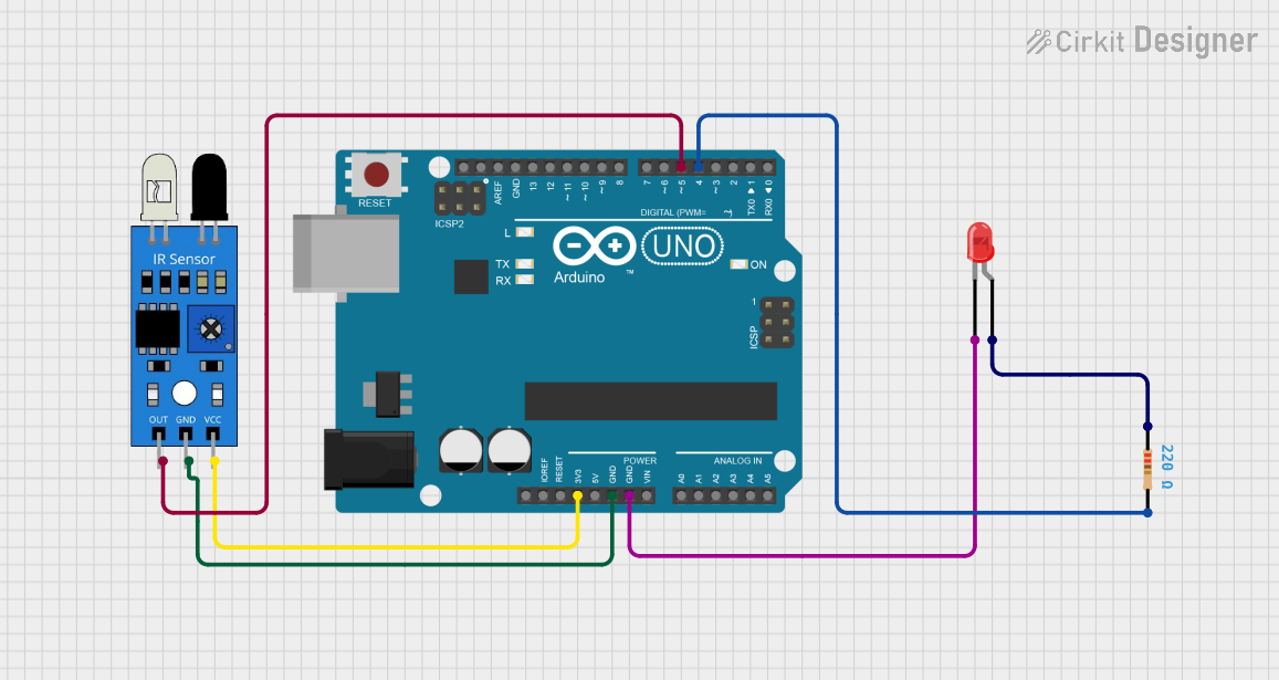
Example: Using an IR LED with Arduino UNO
Below is an example of how to use an IR LED with an Arduino UNO to create a simple IR transmitter.
Circuit Diagram
- Connect the anode of the IR LED to a 220-ohm resistor.
- Connect the other end of the resistor to Arduino pin 3.
- Connect the cathode of the IR LED to the Arduino GND pin.
Code Example
// Simple IR LED Blinking Example
// This code toggles an IR LED on and off every second.

const int irLedPin = 3; // IR LED connected to digital pin 3

void setup() {
  pinMode(irLedPin, OUTPUT); // Set the IR LED pin as an output
}

void loop() {
  digitalWrite(irLedPin, HIGH); // Turn the IR LED on
  delay(1000);                  // Wait for 1 second
  digitalWrite(irLedPin, LOW);  // Turn the IR LED off
  delay(1000);                  // Wait for 1 second
}
Best Practices
- Use a transistor or MOSFET to drive the IR LED if higher currents are required.
- Pair the IR LED with a photodiode or IR receiver module for communication or sensing applications.
- Avoid exposing the IR LED to excessive voltage or current to ensure longevity.
Troubleshooting and FAQs
Common Issues
IR LED Not Emitting Light:
- Cause: Incorrect polarity or insufficient current.
- Solution: Verify the connections and ensure the resistor value allows sufficient current.
IR LED Overheating:
- Cause: Excessive current or power dissipation.
- Solution: Use a higher-value resistor to limit the current.
IR LED Not Detected by Receiver:
- Cause: Misalignment or incompatible wavelength.
- Solution: Align the IR LED and receiver properly and ensure they operate at the same wavelength.
IR LED Not Visible to Camera:
- Cause: Faulty LED or incorrect circuit.
- Solution: Test the LED with a multimeter in diode mode or replace it.
FAQs
Q: Can I use an IR LED without a resistor?
A: No, using an IR LED without a resistor can result in excessive current flow, potentially damaging the LED.
Q: How do I increase the range of an IR LED?
A: Use a higher current (within the LED's maximum rating) or a lens to focus the IR beam.
Q: Can I use an IR LED for data transmission?
A: Yes, IR LEDs are commonly used for transmitting data in remote controls and communication systems. Pair it with an appropriate IR receiver for this purpose.