Cirkit Designer Logo
Cirkit Designer
Your all-in-one circuit design IDE
Home / 
Component Documentation

How to Use Ultrasonic - PING 28015: Examples, Pinouts, and Specs

Image of Ultrasonic - PING 28015
Cirkit Designer LogoDesign with Ultrasonic - PING 28015 in Cirkit Designer

Introduction

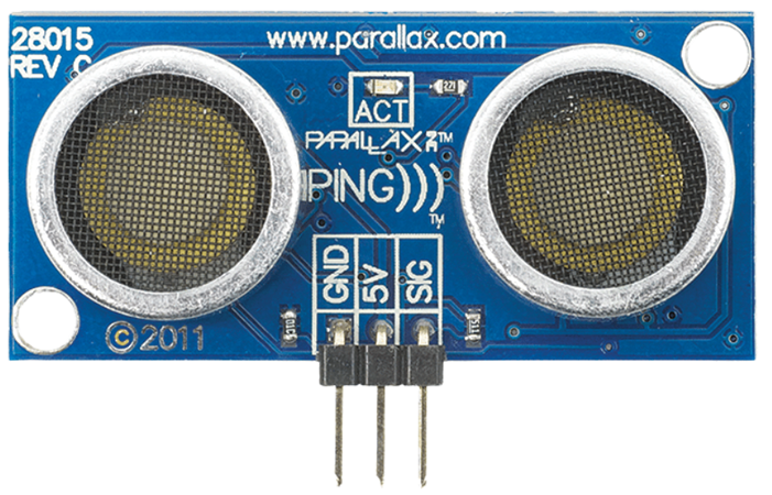
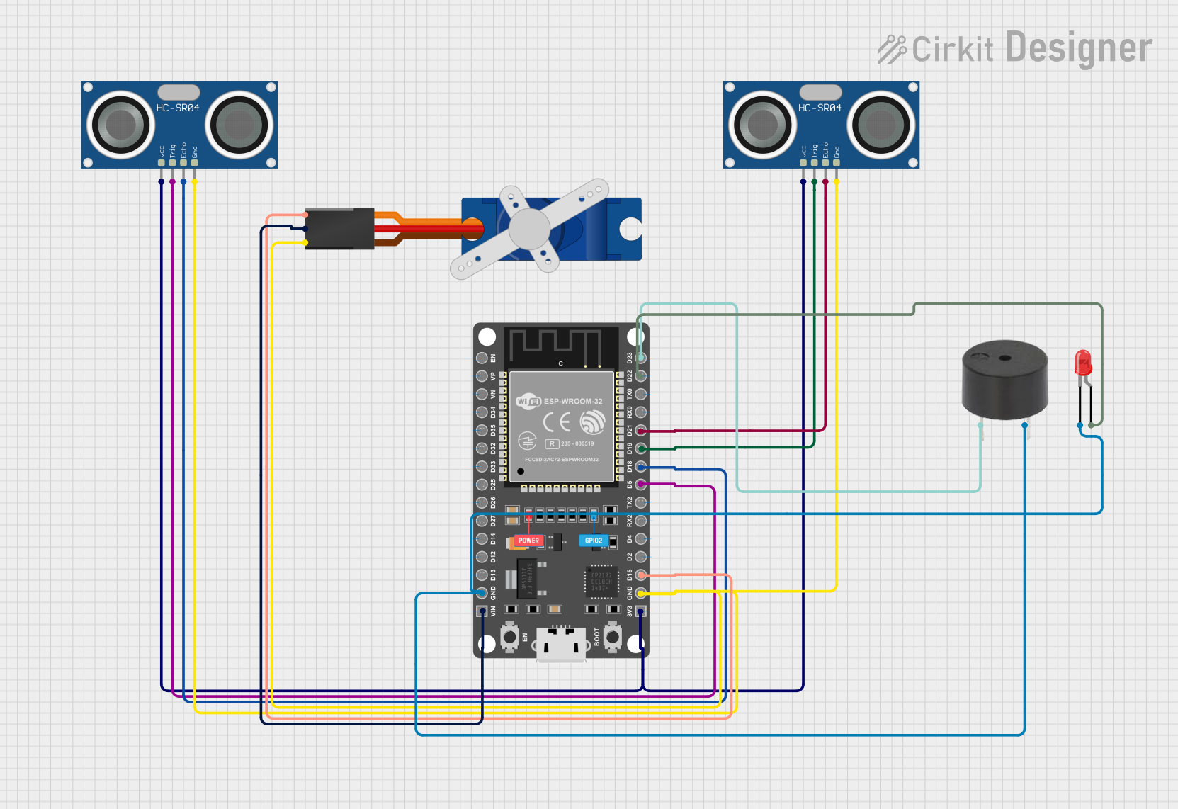
The PING 28015 is an ultrasonic distance sensor manufactured by Parallax. It measures the distance to an object by emitting ultrasonic sound waves and calculating the time it takes for the echo to return. This sensor is widely used in robotics, automation, and other applications requiring precise distance measurement or obstacle detection.

Explore Projects Built with Ultrasonic - PING 28015

Use Cirkit Designer to design, explore, and prototype these projects online. Some projects support real-time simulation. Click "Open Project" to start designing instantly!
Arduino Mega 2560 Bluetooth-Controlled Ultrasonic Distance Measurement
Image of circuitcycle: A project utilizing Ultrasonic - PING 28015 in a practical application
This circuit features an Arduino Mega 2560 microcontroller interfaced with an HC-05 Bluetooth Module and an HC-SR04 Ultrasonic Sensor. The HC-05 is powered by the Arduino's VIN pin and is grounded to the Arduino's GND, enabling wireless communication capabilities. The HC-SR04 is powered by the Arduino's 5V output and uses two digital PWM pins (D7 for TRIG and D6 for ECHO) to measure distances via ultrasonic waves.
Cirkit Designer LogoOpen Project in Cirkit Designer
ESP32-Controlled Robot with Triple Ultrasonic Sensors and L298N Motor Driver
Image of MBo: A project utilizing Ultrasonic - PING 28015 in a practical application
This circuit features an ESP32 microcontroller connected to three HC-SR04 ultrasonic sensors and an L298N motor driver. The ultrasonic sensors are likely used for distance measurement or obstacle detection, with their trigger and echo pins connected to specific GPIOs on the ESP32. The motor driver is interfaced with the ESP32 to control two DC gearmotors, suggesting that this circuit is part of a mobile robot or a similar automated vehicle that requires distance sensing and motor control.
Cirkit Designer LogoOpen Project in Cirkit Designer
Capacitive Touch and Ultrasonic Sensor Interface with Adafruit Feather nRF52840 Sense
Image of Senior Design Project: A project utilizing Ultrasonic - PING 28015 in a practical application
This circuit features an Adafruit Feather nRF52840 Sense microcontroller connected to an ultrasonic sensor for distance measurement and an Adafruit AT42QT1010 capacitive touch sensor for touch input. The ultrasonic sensor's Trigger and Echo pins are interfaced with the microcontroller's digital pins D6 and D9, respectively, to send and receive ultrasonic signals. Additionally, a pressure-sensitive conductive sheet (Velostat) is connected in series with a 10k Ohm resistor to the microcontroller's analog pin A0, likely forming a pressure sensor.
Cirkit Designer LogoOpen Project in Cirkit Designer
ESP32-Based Ultrasonic Distance Measurement with Servo Control and Alert System
Image of Manhole Detector: A project utilizing Ultrasonic - PING 28015 in a practical application
This circuit features an ESP32 microcontroller connected to two HC-SR04 ultrasonic sensors, a Tower Pro SG90 servo motor, a buzzer, and an LED. The ESP32 controls the servo motor via a signal connection on pin D15 and interfaces with the ultrasonic sensors through pins D5, D18, D19, and D21 for triggering and receiving echo signals. The LED and buzzer are connected to pins D22 and D23 respectively, allowing the ESP32 to activate visual and auditory indicators.
Cirkit Designer LogoOpen Project in Cirkit Designer

Explore Projects Built with Ultrasonic - PING 28015

Use Cirkit Designer to design, explore, and prototype these projects online. Some projects support real-time simulation. Click "Open Project" to start designing instantly!
Image of circuitcycle: A project utilizing Ultrasonic - PING 28015 in a practical application
Arduino Mega 2560 Bluetooth-Controlled Ultrasonic Distance Measurement
This circuit features an Arduino Mega 2560 microcontroller interfaced with an HC-05 Bluetooth Module and an HC-SR04 Ultrasonic Sensor. The HC-05 is powered by the Arduino's VIN pin and is grounded to the Arduino's GND, enabling wireless communication capabilities. The HC-SR04 is powered by the Arduino's 5V output and uses two digital PWM pins (D7 for TRIG and D6 for ECHO) to measure distances via ultrasonic waves.
Cirkit Designer LogoOpen Project in Cirkit Designer
Image of MBo: A project utilizing Ultrasonic - PING 28015 in a practical application
ESP32-Controlled Robot with Triple Ultrasonic Sensors and L298N Motor Driver
This circuit features an ESP32 microcontroller connected to three HC-SR04 ultrasonic sensors and an L298N motor driver. The ultrasonic sensors are likely used for distance measurement or obstacle detection, with their trigger and echo pins connected to specific GPIOs on the ESP32. The motor driver is interfaced with the ESP32 to control two DC gearmotors, suggesting that this circuit is part of a mobile robot or a similar automated vehicle that requires distance sensing and motor control.
Cirkit Designer LogoOpen Project in Cirkit Designer
Image of Senior Design Project: A project utilizing Ultrasonic - PING 28015 in a practical application
Capacitive Touch and Ultrasonic Sensor Interface with Adafruit Feather nRF52840 Sense
This circuit features an Adafruit Feather nRF52840 Sense microcontroller connected to an ultrasonic sensor for distance measurement and an Adafruit AT42QT1010 capacitive touch sensor for touch input. The ultrasonic sensor's Trigger and Echo pins are interfaced with the microcontroller's digital pins D6 and D9, respectively, to send and receive ultrasonic signals. Additionally, a pressure-sensitive conductive sheet (Velostat) is connected in series with a 10k Ohm resistor to the microcontroller's analog pin A0, likely forming a pressure sensor.
Cirkit Designer LogoOpen Project in Cirkit Designer
Image of Manhole Detector: A project utilizing Ultrasonic - PING 28015 in a practical application
ESP32-Based Ultrasonic Distance Measurement with Servo Control and Alert System
This circuit features an ESP32 microcontroller connected to two HC-SR04 ultrasonic sensors, a Tower Pro SG90 servo motor, a buzzer, and an LED. The ESP32 controls the servo motor via a signal connection on pin D15 and interfaces with the ultrasonic sensors through pins D5, D18, D19, and D21 for triggering and receiving echo signals. The LED and buzzer are connected to pins D22 and D23 respectively, allowing the ESP32 to activate visual and auditory indicators.
Cirkit Designer LogoOpen Project in Cirkit Designer

Common Applications

  • Obstacle detection in robotics
  • Distance measurement in automation systems
  • Proximity sensing in security systems
  • Object tracking in smart devices

Technical Specifications

The PING 28015 sensor is designed for ease of use and reliable performance. Below are its key technical details:

Parameter Value
Operating Voltage 5 V DC
Operating Current 30 mA (typical)
Measurement Range 2 cm to 3 m
Measurement Resolution 2 mm
Signal Frequency 40 kHz
Interface Single I/O pin for trigger/echo
Dimensions 22 mm x 46 mm x 16 mm
Operating Temperature 0°C to 70°C

Pin Configuration

The PING 28015 has a 3-pin interface for power, ground, and signal. Below is the pinout:

Pin Name Description
1 VCC Power supply input (5 V DC)
2 SIG Signal pin for both trigger and echo (bidirectional)
3 GND Ground connection

Usage Instructions

The PING 28015 sensor is simple to use and requires only one I/O pin for operation. Below are the steps to integrate it into a circuit and use it effectively:

Circuit Connection

  1. Connect the VCC pin to a 5 V power supply.
  2. Connect the GND pin to the ground of your circuit.
  3. Connect the SIG pin to a digital I/O pin on your microcontroller (e.g., Arduino UNO).

How It Works

  1. The microcontroller sends a short HIGH pulse (minimum 2 µs) to the SIG pin to trigger the sensor.

  2. The sensor emits an ultrasonic pulse and waits for the echo to return.

  3. The sensor outputs a HIGH pulse on the SIG pin, where the duration of the pulse corresponds to the time taken for the echo to return.

  4. The microcontroller measures the duration of the HIGH pulse and calculates the distance using the formula:

    [ \text{Distance (cm)} = \frac{\text{Pulse Duration (µs)}}{58} ]

Arduino UNO Example Code

Below is an example code to use the PING 28015 with an Arduino UNO:

// Define the pin connected to the SIG pin of the PING 28015
const int pingPin = 7;

void setup() {
  Serial.begin(9600); // Initialize serial communication at 9600 baud
}

void loop() {
  long duration, distance;

  // Send a 2 µs HIGH pulse to trigger the sensor
  pinMode(pingPin, OUTPUT);
  digitalWrite(pingPin, LOW);
  delayMicroseconds(2);
  digitalWrite(pingPin, HIGH);
  delayMicroseconds(5);
  digitalWrite(pingPin, LOW);

  // Set the pin to input mode to read the echo
  pinMode(pingPin, INPUT);
  duration = pulseIn(pingPin, HIGH);

  // Calculate the distance in cm
  distance = duration / 58;

  // Print the distance to the Serial Monitor
  Serial.print("Distance: ");
  Serial.print(distance);
  Serial.println(" cm");

  delay(100); // Wait 100 ms before the next measurement
}

Best Practices

  • Ensure the sensor is mounted securely to avoid vibrations that may affect accuracy.
  • Avoid placing the sensor near ultrasonic noise sources (e.g., other ultrasonic sensors).
  • Use a decoupling capacitor (e.g., 10 µF) across the power supply pins to reduce noise.

Troubleshooting and FAQs

Common Issues and Solutions

  1. No Output or Incorrect Readings

    • Ensure the sensor is powered with 5 V DC.
    • Verify the connections to the microcontroller are correct.
    • Check for loose or damaged wires.
  2. Inconsistent Distance Measurements

    • Ensure there are no obstructions or reflective surfaces near the sensor.
    • Avoid using the sensor in environments with high ultrasonic noise.
  3. Sensor Not Responding

    • Confirm the microcontroller is sending a proper trigger pulse (minimum 2 µs).
    • Check the SIG pin for proper signal levels using an oscilloscope or logic analyzer.

FAQs

Q: Can the PING 28015 detect transparent objects?
A: The sensor may have difficulty detecting transparent or very small objects due to poor ultrasonic reflection.

Q: What is the maximum range of the sensor?
A: The maximum range is 3 meters, but accuracy may decrease at longer distances.

Q: Can I use multiple PING 28015 sensors in the same project?
A: Yes, but ensure they are triggered sequentially to avoid interference between sensors.

Q: Is the PING 28015 compatible with 3.3 V microcontrollers?
A: The sensor requires a 5 V power supply, but the SIG pin can interface with 3.3 V logic levels. Use a level shifter if needed.