
How to Use Adafruit I2S Mic - SPH0645: Examples, Pinouts, and Specs
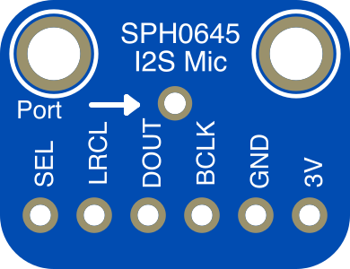
 Design with Adafruit I2S Mic - SPH0645 in Cirkit Designer
Introduction
The Adafruit I2S Mic (Manufacturer Part ID: 3421) is a digital microphone that utilizes the I2S (Inter-IC Sound) interface for transmitting audio data. This component is designed to deliver high-quality sound capture with low power consumption, making it an excellent choice for applications such as voice recognition, audio processing, and sound recording. Unlike analog microphones, the I2S Mic outputs digital audio data, eliminating the need for an analog-to-digital converter (ADC).
Explore Projects Built with Adafruit I2S Mic - SPH0645
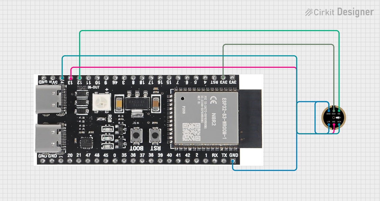 Open Project in Cirkit Designer
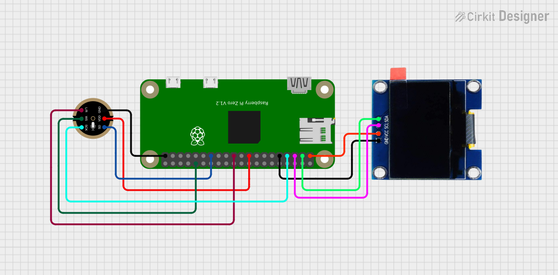 Open Project in Cirkit Designer
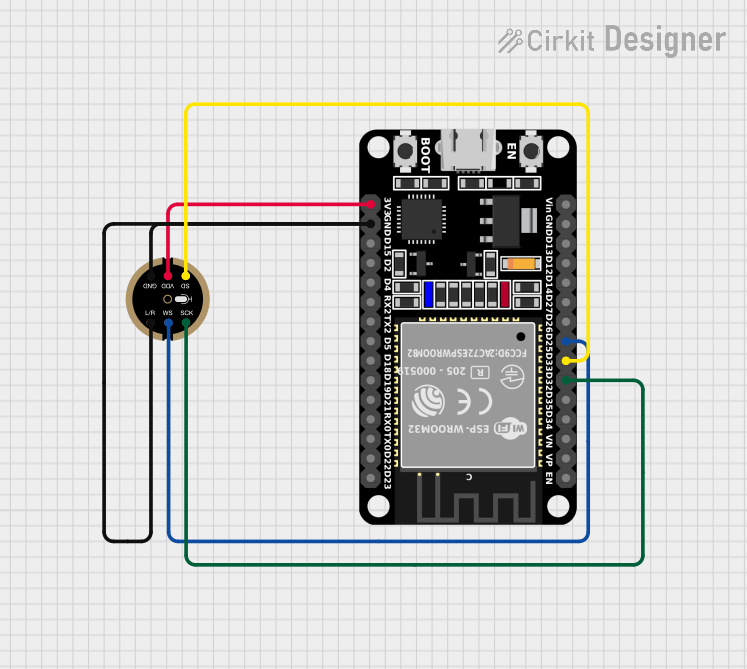 Open Project in Cirkit Designer
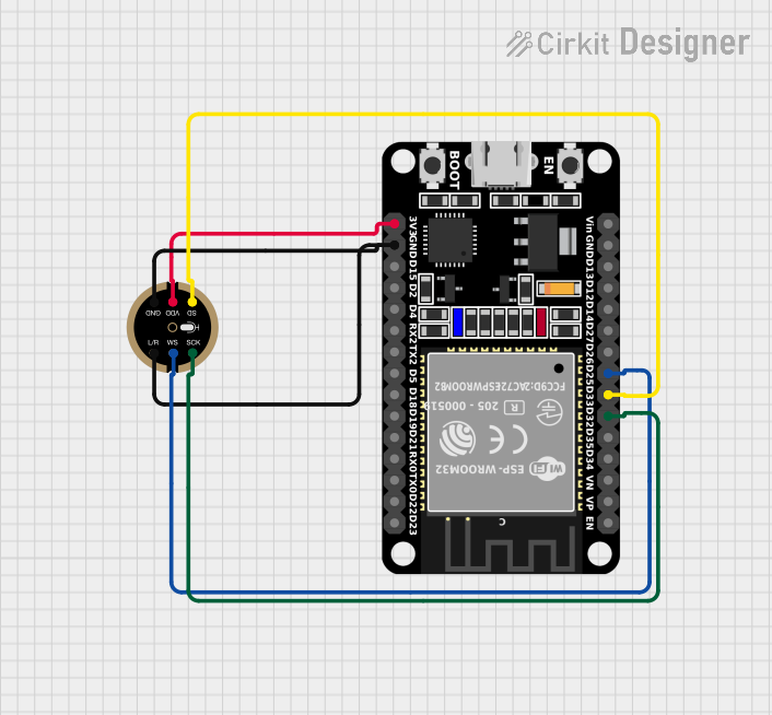 Open Project in Cirkit Designer
Explore Projects Built with Adafruit I2S Mic - SPH0645
Open Project in Cirkit DesignerOpen Project in Cirkit DesignerOpen Project in Cirkit DesignerOpen Project in Cirkit DesignerCommon Applications
- Voice recognition systems
- Audio recording and playback devices
- IoT devices with sound detection capabilities
- Smart home assistants
- Audio spectrum analysis projects
Technical Specifications
The Adafruit I2S Mic - SPH0645 is designed for ease of use and high performance. Below are its key technical details:
Key Specifications
| Parameter | Value |
|---|---|
| Operating Voltage | 1.8V to 3.3V |
| Interface | I2S (Inter-IC Sound) |
| Sampling Rates | 32kHz, 44.1kHz, 48kHz |
| Bit Depth | 24-bit |
| Power Consumption | Low power (approx. 1mA) |
| Signal-to-Noise Ratio | 65 dB |
| Sensitivity | -26 dBFS ±3 dB |
| Dimensions | 15mm x 11mm x 1.5mm |
Pin Configuration
The Adafruit I2S Mic has four pins, as described in the table below:
| Pin Name | Description |
|---|---|
| VIN | Power input (1.8V to 3.3V). Connect to the 3.3V pin of your microcontroller. |
| GND | Ground. Connect to the ground of your circuit. |
| BCLK | Bit Clock. Provides the clock signal for data transmission. |
| DOUT | Data Output. Outputs the digital audio data in I2S format. |
Usage Instructions
The Adafruit I2S Mic is straightforward to use in audio projects. Below are the steps and considerations for integrating it into your circuit.
Connecting the I2S Mic
- Power Supply: Connect the
VINpin to a 3.3V power source and theGNDpin to ground. - I2S Interface:
- Connect the
BCLKpin to the Bit Clock (BCLK) pin of your microcontroller. - Connect the
DOUTpin to the Data Input (DIN) pin of your microcontroller.
- Connect the
- Configuration: Ensure your microcontroller supports I2S communication and configure it to match the microphone's sampling rate and bit depth.
Important Considerations
- Voltage Levels: The microphone operates at 3.3V logic levels. Ensure your microcontroller is compatible or use a level shifter if necessary.
- Sampling Rate: Choose a sampling rate supported by the microphone (e.g., 44.1kHz) for optimal performance.
- Microphone Placement: Place the microphone away from noise sources (e.g., power supplies) to minimize interference.
Example: Using with Arduino UNO
The Adafruit I2S Mic can be used with an Arduino-compatible board that supports I2S, such as the Arduino Nano 33 IoT. Below is an example code snippet for capturing audio data:
#include <I2S.h> // Include the I2S library for audio data handling

void setup() {
  Serial.begin(115200); // Initialize serial communication for debugging
  while (!Serial);

  // Initialize I2S for receiving audio data
  if (!I2S.begin(I2S_PHILIPS_MODE, 44100, 32)) {
    Serial.println("Failed to initialize I2S!");
    while (1); // Halt execution if I2S initialization fails
  }

  Serial.println("I2S Microphone Initialized");
}

void loop() {
  int sample = 0;

  // Check if audio data is available
  if (I2S.available()) {
    sample = I2S.read(); // Read a 32-bit audio sample
    Serial.println(sample); // Print the audio sample to the Serial Monitor
  }
}
Notes on the Code
- The
I2S.begin()function initializes the I2S interface in Philips mode with a 44.1kHz sampling rate and 32-bit depth. - The
I2S.read()function retrieves audio samples from the microphone.
Troubleshooting and FAQs
Common Issues
No Audio Data Output
- Cause: Incorrect wiring or configuration.
- Solution: Double-check the connections, especially the
BCLKandDOUTpins. Ensure the microcontroller is configured for I2S communication.
Distorted Audio
- Cause: Incorrect sampling rate or bit depth.
- Solution: Verify that the sampling rate and bit depth in your code match the microphone's specifications.
Microphone Not Detected
- Cause: Power supply issues or incompatible logic levels.
- Solution: Ensure the
VINpin is receiving 3.3V and the microcontroller supports 3.3V logic levels.
FAQs
Q: Can I use the I2S Mic with a 5V microcontroller?
A: The microphone operates at 3.3V logic levels. If your microcontroller uses 5V logic, you will need a level shifter to safely interface with the microphone.
Q: What is the maximum sampling rate supported by the microphone?
A: The Adafruit I2S Mic supports sampling rates up to 48kHz.
Q: Can I use multiple I2S microphones in a single project?
A: Yes, but you will need a microcontroller with multiple I2S interfaces or a way to multiplex the I2S signals.
By following this documentation, you can effectively integrate the Adafruit I2S Mic - SPH0645 into your audio projects for high-quality sound capture and processing.