How to Use max30003: Examples, Pinouts, and Specs
Introduction
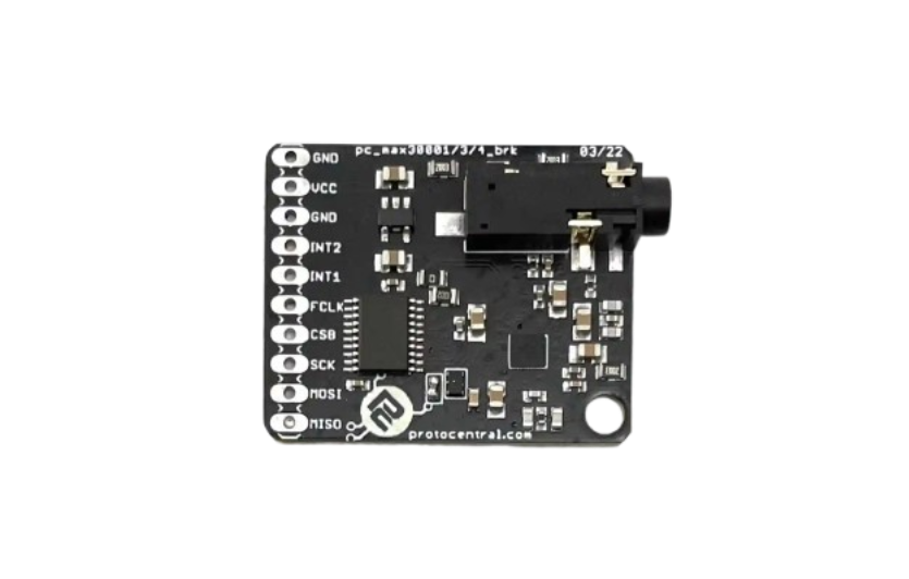
The MAX30003, manufactured by Protocentral, is a highly integrated, low-power biopotential measurement IC designed for precise ECG (electrocardiogram) and other medical applications. It features a low-noise instrumentation amplifier, a 24-bit analog-to-digital converter (ADC), and integrated lead-off detection. These features make it ideal for wearable health monitoring devices, portable ECG systems, and other medical-grade applications requiring accurate biopotential measurements.
Explore Projects Built with max30003


Explore Projects Built with max30003
Common Applications and Use Cases
- Wearable health monitoring devices
- Portable ECG systems
- Fitness trackers with heart rate monitoring
- Medical-grade diagnostic equipment
- Research and development in biopotential signal processing
Technical Specifications
Key Technical Details
| Parameter | Value |
|---|---|
| Supply Voltage | 1.1V (core), 1.8V to 3.6V (I/O) |
| Power Consumption | 85µW (typical, at 1.1V supply) |
| Input Impedance | >500MΩ |
| ADC Resolution | 24-bit |
| Input Signal Range | ±300mV |
| Common-Mode Rejection Ratio | 100dB |
| Lead-Off Detection | Integrated |
| Operating Temperature Range | -40°C to +85°C |
| Package Type | 20-pin TQFN (5mm x 5mm) |
Pin Configuration and Descriptions
The MAX30003 comes in a 20-pin TQFN package. Below is the pin configuration and description:
| Pin Number | Pin Name | Description |
|---|---|---|
| 1 | VDDIO | Digital I/O supply voltage |
| 2 | VCORE | Core supply voltage |
| 3 | GND | Ground |
| 4 | INP | Positive ECG input |
| 5 | INN | Negative ECG input |
| 6 | REF | Reference voltage output |
| 7 | LOFF | Lead-off detection output |
| 8 | CS | Chip select for SPI communication |
| 9 | SCLK | SPI clock input |
| 10 | MISO | SPI master-in-slave-out |
| 11 | MOSI | SPI master-out-slave-in |
| 12 | RST | Reset input (active low) |
| 13-20 | NC | No connection |
Usage Instructions
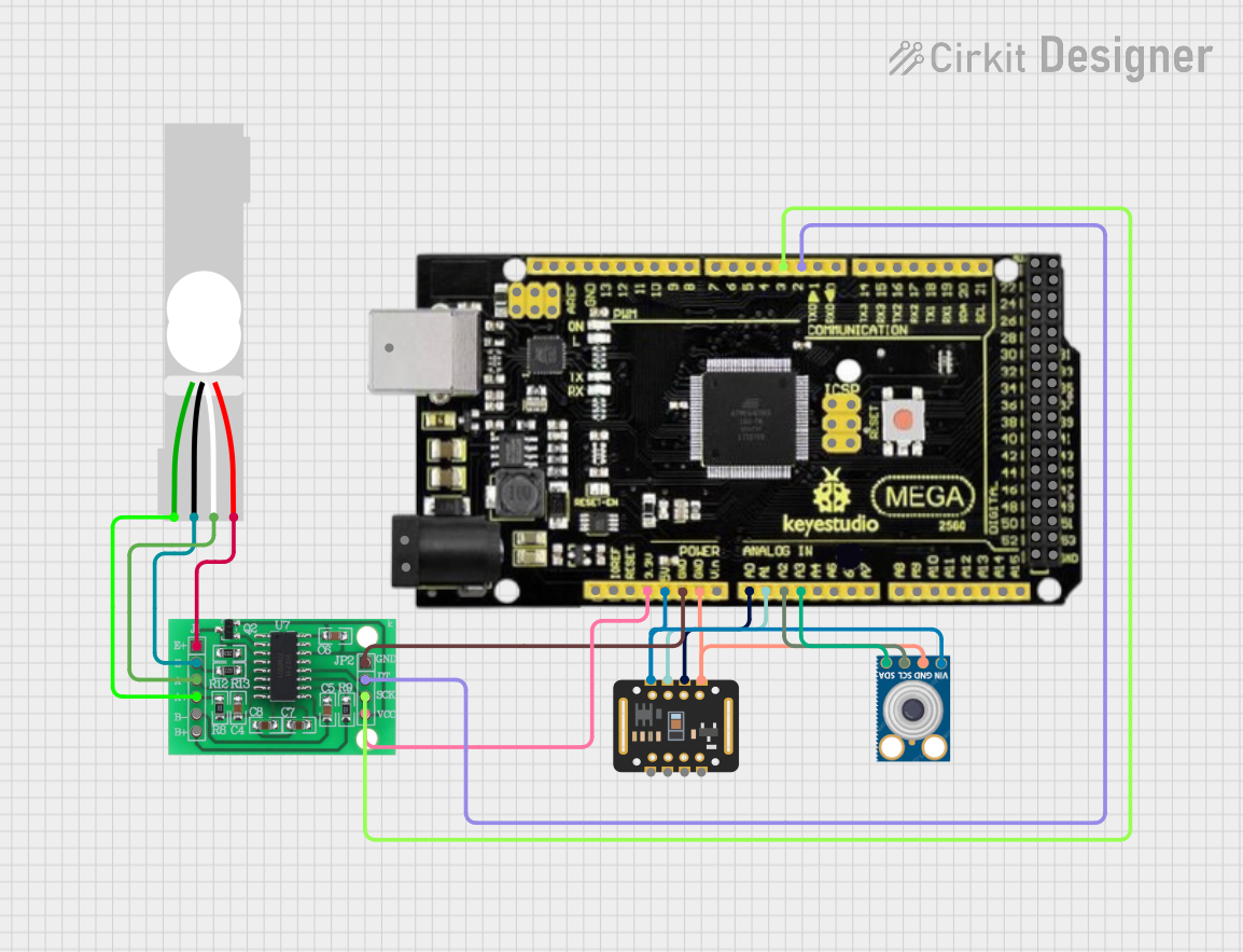
How to Use the MAX30003 in a Circuit
- Power Supply: Connect the VDDIO pin to a 1.8V to 3.6V supply and the VCORE pin to a 1.1V supply. Ensure proper decoupling capacitors are placed close to the pins.
- Input Connections: Connect the biopotential electrodes to the INP and INN pins. Use proper filtering and protection circuitry to ensure signal integrity.
- SPI Communication: Interface the MAX30003 with a microcontroller using the SPI pins (CS, SCLK, MISO, MOSI). Configure the SPI clock speed and mode as per the datasheet.
- Lead-Off Detection: Use the LOFF pin to monitor electrode connectivity. This feature helps detect if an electrode is disconnected.
- Reference Voltage: The REF pin provides a stable reference voltage for the ADC. Ensure it is properly decoupled.
Important Considerations and Best Practices
- Use high-quality, low-noise power supplies to minimize interference in ECG signals.
- Place the MAX30003 as close as possible to the electrodes to reduce noise and signal degradation.
- Use proper grounding techniques to avoid ground loops and improve signal quality.
- Implement software filtering to remove motion artifacts and baseline wander in ECG signals.
- Follow the manufacturer's guidelines for PCB layout to ensure optimal performance.
Example Code for Arduino UNO
Below is an example of how to interface the MAX30003 with an Arduino UNO using SPI:
#include <SPI.h>

// Define MAX30003 SPI pins
#define MAX30003_CS 10  // Chip select pin for MAX30003

void setup() {
  // Initialize serial communication for debugging
  Serial.begin(9600);

  // Initialize SPI communication
  SPI.begin();
  pinMode(MAX30003_CS, OUTPUT);
  digitalWrite(MAX30003_CS, HIGH); // Set CS pin high (inactive)

  // Reset the MAX30003
  resetMAX30003();
}

void loop() {
  // Example: Read a register from MAX30003
  uint8_t regAddress = 0x01; // Replace with the desired register address
  uint32_t regValue = readRegister(regAddress);
  Serial.print("Register Value: 0x");
  Serial.println(regValue, HEX);

  delay(1000); // Wait for 1 second
}

// Function to reset the MAX30003
void resetMAX30003() {
  digitalWrite(MAX30003_CS, LOW); // Activate CS
  SPI.transfer(0x08); // Reset command (example)
  digitalWrite(MAX30003_CS, HIGH); // Deactivate CS
}

// Function to read a 24-bit register from MAX30003
uint32_t readRegister(uint8_t regAddress) {
  uint32_t value = 0;

  digitalWrite(MAX30003_CS, LOW); // Activate CS
  SPI.transfer(regAddress); // Send register address
  value |= SPI.transfer(0x00) << 16; // Read MSB
  value |= SPI.transfer(0x00) << 8;  // Read middle byte
  value |= SPI.transfer(0x00);       // Read LSB
  digitalWrite(MAX30003_CS, HIGH); // Deactivate CS

  return value;
}
Troubleshooting and FAQs
Common Issues and Solutions
No Output from the MAX30003:
- Cause: Incorrect power supply or SPI configuration.
- Solution: Verify the power supply voltages and ensure SPI settings (clock speed, mode) match the datasheet.
High Noise in ECG Signal:
- Cause: Poor grounding or improper filtering.
- Solution: Check the grounding scheme and add appropriate filters to the input.
Lead-Off Detection Not Working:
- Cause: Incorrect configuration or disconnected electrodes.
- Solution: Verify the LOFF pin configuration and ensure electrodes are properly connected.
SPI Communication Fails:
- Cause: Incorrect wiring or chip select handling.
- Solution: Double-check SPI connections and ensure the CS pin is toggled correctly.
FAQs
Can the MAX30003 be used for other biopotential measurements?
- Yes, it can measure other biopotential signals, but it is optimized for ECG applications.
What is the maximum sampling rate of the ADC?
- The ADC supports a maximum sampling rate of 128Hz, suitable for ECG applications.
Is the MAX30003 suitable for battery-powered devices?
- Yes, its low power consumption makes it ideal for battery-powered wearable devices.
Can I use the MAX30003 with a 5V microcontroller?
- Yes, but ensure the microcontroller's SPI pins are level-shifted to 3.3V or lower to avoid damaging the MAX30003.