Cirkit Designer
Your all-in-one circuit design IDE
Home /
Component Documentation
How to Use FTDI: Examples, Pinouts, and Specs
Introduction
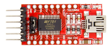
The FTDI (Future Technology Devices International) USB-to-Serial interface chip is a versatile component designed to convert USB signals to various serial communication protocols such as UART, SPI, and I2C. This chip is widely used in applications where a USB interface is required to communicate with microcontrollers, sensors, and other serial devices. Common use cases include:
- USB-to-serial adapters
- Microcontroller programming
- Data logging and communication with sensors
- Debugging and development tools
Explore Projects Built with FTDI
FTDI to UART Adapter with J26 Connector

This circuit connects an FTDI USB-to-serial converter to a standard serial interface via a J26 connector. It facilitates serial communication by linking the ground, transmit, receive, data terminal ready, and request to send signals between the FTDI chip and the J26 connector.
ESP8266 WiFi Module Serial Interface with Pushbutton Control

This circuit features an ESP8266 ESP-01 WiFi module interfaced with an Adafruit FTDI Friend for serial communication. The ESP8266's TXD and RXD pins are connected to the FTDI's RX and TX pins respectively, allowing for data exchange between the microcontroller and a computer. Additionally, a pushbutton is connected to the ESP8266's reset pin, enabling manual resets of the module.
ATMEGA328 Microcontroller Circuit with Serial Programming Interface

This circuit features an ATMEGA328 microcontroller configured with a crystal oscillator for precise timing, and a pushbutton for reset functionality. An FTDI Programmer is connected for serial communication, allowing for programming and data exchange with the microcontroller.
ESP32-CAM FTDI Interface for Serial Communication
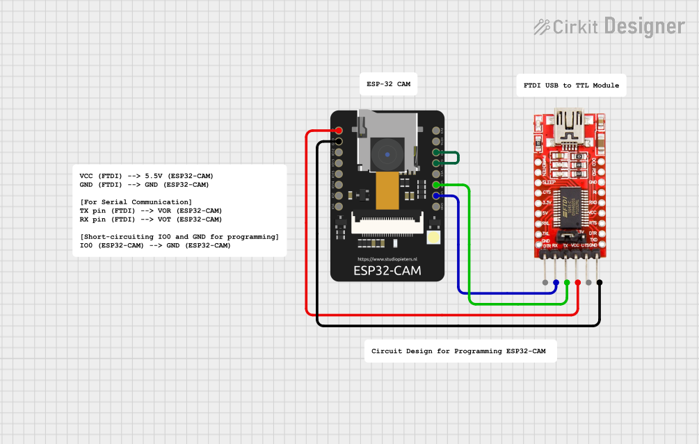
This circuit connects an ESP32-CAM module with an FTDI Programmer for serial communication and programming. The 5V and GND pins of the ESP32-CAM are connected to the VCC and GND of the FTDI to provide power. The TX and RX pins of the ESP32-CAM are connected to the RX and TX pins of the FTDI, respectively, to enable serial data transfer. Additionally, the IO0 pin of the ESP32-CAM is grounded, likely to put the module into flashing mode for programming.
Explore Projects Built with FTDI
FTDI to UART Adapter with J26 Connector
This circuit connects an FTDI USB-to-serial converter to a standard serial interface via a J26 connector. It facilitates serial communication by linking the ground, transmit, receive, data terminal ready, and request to send signals between the FTDI chip and the J26 connector.
ESP8266 WiFi Module Serial Interface with Pushbutton Control
This circuit features an ESP8266 ESP-01 WiFi module interfaced with an Adafruit FTDI Friend for serial communication. The ESP8266's TXD and RXD pins are connected to the FTDI's RX and TX pins respectively, allowing for data exchange between the microcontroller and a computer. Additionally, a pushbutton is connected to the ESP8266's reset pin, enabling manual resets of the module.
ATMEGA328 Microcontroller Circuit with Serial Programming Interface
This circuit features an ATMEGA328 microcontroller configured with a crystal oscillator for precise timing, and a pushbutton for reset functionality. An FTDI Programmer is connected for serial communication, allowing for programming and data exchange with the microcontroller.
ESP32-CAM FTDI Interface for Serial Communication
This circuit connects an ESP32-CAM module with an FTDI Programmer for serial communication and programming. The 5V and GND pins of the ESP32-CAM are connected to the VCC and GND of the FTDI to provide power. The TX and RX pins of the ESP32-CAM are connected to the RX and TX pins of the FTDI, respectively, to enable serial data transfer. Additionally, the IO0 pin of the ESP32-CAM is grounded, likely to put the module into flashing mode for programming.
Technical Specifications
Key Technical Details
| Parameter | Value |
|---|---|
| Supply Voltage | 3.3V or 5V |
| Operating Current | 15mA (typical) |
| Communication | UART, SPI, I2C |
| Data Rate | Up to 3 Mbps (UART) |
| USB Standard | USB 2.0 Full Speed |
| Operating Temperature | -40°C to +85°C |
| Package Types | SSOP-28, QFN-32, LQFP-48 |
Pin Configuration and Descriptions
SSOP-28 Package
| Pin No. | Name | Type | Description |
|---|---|---|---|
| 1 | TXD | Output | Transmit Data (UART) |
| 2 | RXD | Input | Receive Data (UART) |
| 3 | RTS# | Output | Request to Send (Active Low) |
| 4 | CTS# | Input | Clear to Send (Active Low) |
| 5 | DTR# | Output | Data Terminal Ready (Active Low) |
| 6 | DSR# | Input | Data Set Ready (Active Low) |
| 7 | DCD# | Input | Data Carrier Detect (Active Low) |
| 8 | RI# | Input | Ring Indicator (Active Low) |
| 9 | GND | Ground | Ground |
| 10 | VCC | Power | Supply Voltage (3.3V or 5V) |
| 11 | USB D+ | I/O | USB Data Positive |
| 12 | USB D- | I/O | USB Data Negative |
| 13 | RESET# | Input | Reset (Active Low) |
| 14 | 3V3OUT | Output | 3.3V Output |
| 15 | CBUS0 | I/O | Configurable I/O Pin 0 |
| 16 | CBUS1 | I/O | Configurable I/O Pin 1 |
| 17 | CBUS2 | I/O | Configurable I/O Pin 2 |
| 18 | CBUS3 | I/O | Configurable I/O Pin 3 |
| 19 | CBUS4 | I/O | Configurable I/O Pin 4 |
| 20 | TEST | Input | Test Pin (Leave Unconnected) |
| 21 | AGND | Ground | Analog Ground |
| 22 | VCCIO | Power | I/O Voltage Supply |
| 23 | TXLED# | Output | Transmit LED (Active Low) |
| 24 | RXLED# | Output | Receive LED (Active Low) |
| 25 | SUSPEND# | Output | Suspend (Active Low) |
| 26 | PWREN# | Output | Power Enable (Active Low) |
| 27 | SLEEP# | Output | Sleep (Active Low) |
| 28 | CLKOUT | Output | Clock Output |
Usage Instructions
How to Use the Component in a Circuit
- Power Supply: Connect the VCC pin to a 3.3V or 5V power supply and the GND pin to ground.
- USB Connection: Connect the USB D+ and USB D- pins to the corresponding USB data lines.
- Serial Communication: Connect the TXD and RXD pins to the corresponding UART pins on your microcontroller or serial device.
- Flow Control (Optional): If using hardware flow control, connect the RTS# and CTS# pins.
- Configurable Pins: Use the CBUS pins for additional I/O functions as needed.
- LED Indicators: Connect the TXLED# and RXLED# pins to LEDs for visual indication of data transmission and reception.
Important Considerations and Best Practices
- Voltage Levels: Ensure that the voltage levels of the FTDI chip match those of the connected devices.
- Decoupling Capacitors: Place decoupling capacitors close to the VCC pin to filter out noise.
- USB Compliance: Follow USB design guidelines to ensure reliable communication.
- Driver Installation: Install the appropriate FTDI drivers on your computer to enable USB-to-serial communication.
Example: Connecting FTDI to Arduino UNO
#include <SoftwareSerial.h>

// RX and TX pins for FTDI
const int RX_PIN = 10;
const int TX_PIN = 11;

// Create a SoftwareSerial object
SoftwareSerial mySerial(RX_PIN, TX_PIN);

void setup() {
  // Start the hardware serial communication
  Serial.begin(9600);
  // Start the software serial communication
  mySerial.begin(9600);
}

void loop() {
  if (mySerial.available()) {
    // Read data from FTDI and send it to the Serial Monitor
    Serial.write(mySerial.read());
  }
  if (Serial.available()) {
    // Read data from Serial Monitor and send it to FTDI
    mySerial.write(Serial.read());
  }
}
Troubleshooting and FAQs
Common Issues Users Might Face
- No Communication: Ensure that the correct drivers are installed and the FTDI chip is properly connected.
- Incorrect Data: Verify that the baud rate and other serial settings match between the FTDI chip and the connected device.
- Device Not Recognized: Check the USB connection and ensure that the FTDI chip is powered correctly.
Solutions and Tips for Troubleshooting
- Driver Issues: Reinstall the FTDI drivers from the official website.
- Connection Problems: Double-check all connections and ensure that there are no loose wires.
- Power Supply: Ensure that the FTDI chip is receiving the correct voltage and that decoupling capacitors are in place.
By following this documentation, users can effectively integrate the FTDI USB-to-Serial interface chip into their projects, ensuring reliable and efficient communication between USB and serial devices.