
How to Use Limit Switch KW12-3: Examples, Pinouts, and Specs
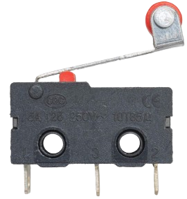
 Design with Limit Switch KW12-3 in Cirkit Designer
Introduction
The Limit Switch KW12-3 is a mechanical switch designed to detect the presence or position of an object. It is commonly used in industrial automation systems, machinery, and safety applications. The switch operates by physically interacting with a moving object, triggering its internal mechanism to open or close an electrical circuit. Its compact design and reliable performance make it a popular choice for applications requiring precise control and safety.
Explore Projects Built with Limit Switch KW12-3
 Open Project in Cirkit Designer
 Open Project in Cirkit Designer
 Open Project in Cirkit Designer
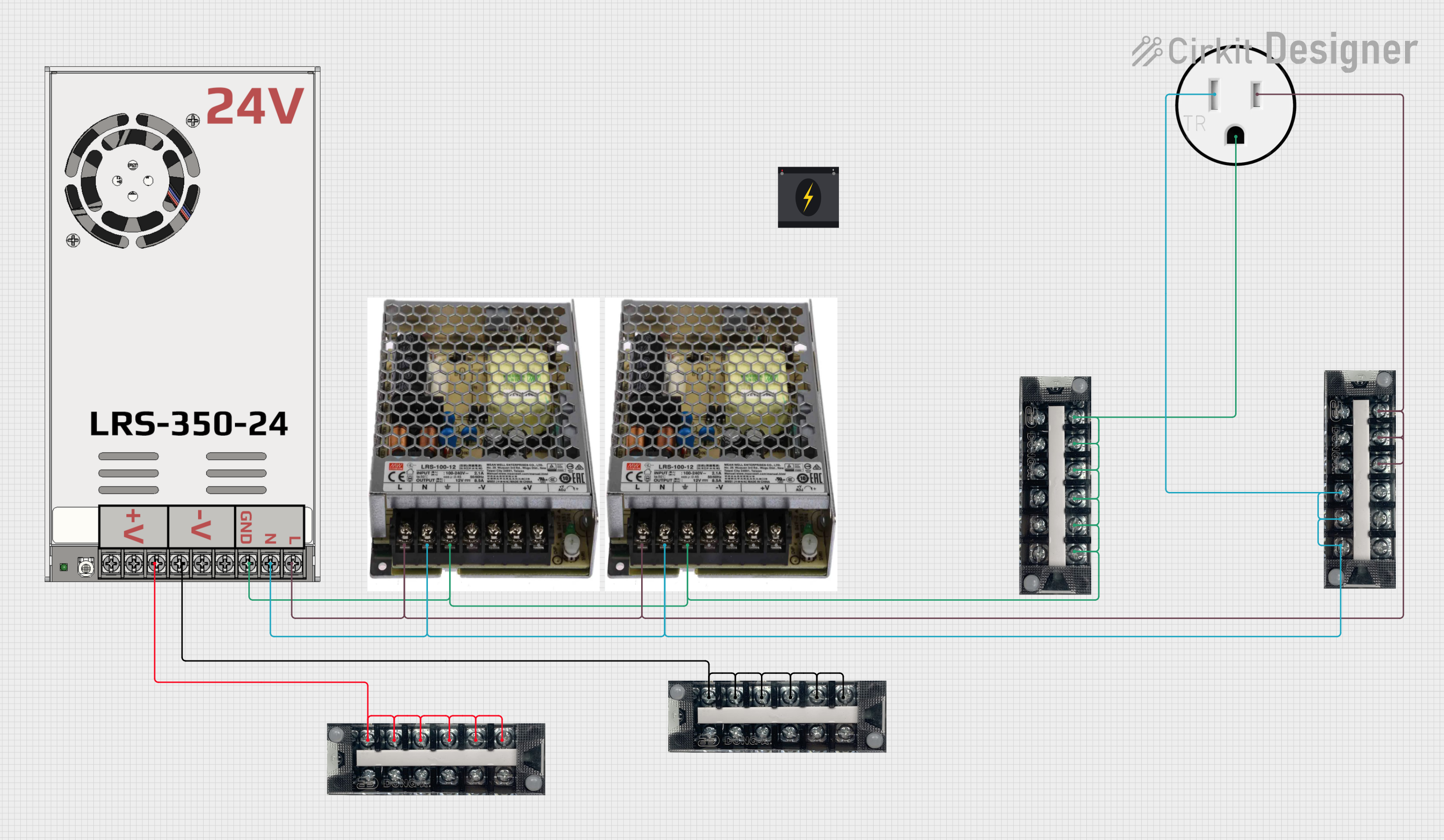 Open Project in Cirkit Designer
Explore Projects Built with Limit Switch KW12-3
Open Project in Cirkit DesignerOpen Project in Cirkit DesignerOpen Project in Cirkit DesignerOpen Project in Cirkit DesignerCommon Applications
- Industrial machinery for position detection
- Safety interlocks in automated systems
- Robotics for end-stop detection
- Elevators and conveyor systems
- Home appliances for mechanical feedback
Technical Specifications
Key Technical Details
| Parameter | Value |
|---|---|
| Model Number | KW12-3 |
| Operating Voltage | 125V AC / 250V AC |
| Rated Current | 5A |
| Contact Configuration | SPDT (Single Pole Double Throw) |
| Mechanical Life | 1,000,000 cycles |
| Electrical Life | 50,000 cycles |
| Operating Force | 50gf (gram-force) |
| Terminal Type | Soldering terminals |
| Operating Temperature | -25°C to +85°C |
| Dimensions | 27.8mm x 10.3mm x 15.9mm |
Pin Configuration and Descriptions
The KW12-3 limit switch has three terminals, corresponding to its SPDT configuration:
| Pin Name | Description |
|---|---|
| COM | Common terminal. This is the main terminal connected to the moving contact. |
| NO | Normally Open terminal. The circuit is open until the switch is activated. |
| NC | Normally Closed terminal. The circuit is closed until the switch is activated. |
Usage Instructions
How to Use the KW12-3 in a Circuit
- Identify the Terminals: Locate the COM, NO, and NC terminals on the switch.
- Connect the Circuit:
- For a circuit that should activate when the switch is pressed, connect the load between COM and NO.
- For a circuit that should deactivate when the switch is pressed, connect the load between COM and NC.
- Mount the Switch: Secure the switch in the desired position using screws or mounting brackets. Ensure the actuator (lever or plunger) aligns with the moving object.
- Test the Operation: Manually press the actuator to verify the circuit behavior.
Important Considerations
- Voltage and Current Ratings: Ensure the connected load does not exceed the switch's rated voltage (250V AC) and current (5A).
- Debouncing: Mechanical switches may produce electrical noise (bouncing) when activated. Use a capacitor or software debouncing techniques in sensitive circuits.
- Environmental Conditions: Avoid exposing the switch to extreme temperatures, moisture, or corrosive environments beyond its specified limits.
- Wiring: Use appropriate gauge wires and ensure secure soldering to the terminals.
Example: Connecting to an Arduino UNO
The KW12-3 can be used with an Arduino UNO for position detection or as an input device. Below is an example of how to connect and program the switch:
Circuit Diagram
- Connect the COM terminal to GND on the Arduino.
- Connect the NO terminal to a digital input pin (e.g., pin 2) on the Arduino.
- Use a pull-up resistor (10kΩ) between the NO terminal and the Arduino's 5V pin.
Arduino Code
// Define the pin connected to the limit switch
const int limitSwitchPin = 2; // Digital pin 2

void setup() {
  pinMode(limitSwitchPin, INPUT_PULLUP);
  // Set the pin as input with an internal pull-up resistor

  Serial.begin(9600);
  // Initialize serial communication for debugging
}

void loop() {
  int switchState = digitalRead(limitSwitchPin);
  // Read the state of the limit switch

  if (switchState == LOW) {
    // LOW indicates the switch is pressed (NO terminal connected to COM)
    Serial.println("Limit switch activated!");
  } else {
    Serial.println("Limit switch not activated.");
  }

  delay(100);
  // Small delay to avoid excessive serial output
}
Notes:
- The internal pull-up resistor in the Arduino simplifies the circuit by eliminating the need for an external resistor.
- Adjust the
delay()value as needed for your application.
Troubleshooting and FAQs
Common Issues and Solutions
| Issue | Possible Cause | Solution |
|---|---|---|
| Switch does not activate the circuit | Incorrect wiring | Verify connections to COM, NO, and NC. |
| Unstable or noisy signal | Contact bouncing | Add a capacitor or implement software debouncing. |
| Switch fails to operate | Exceeded voltage/current ratings | Ensure the load is within rated limits. |
| Physical damage to the actuator | Misalignment or excessive force | Realign the switch and avoid overloading. |
FAQs
Q: Can the KW12-3 handle DC loads?
A: Yes, the KW12-3 can handle DC loads, but ensure the voltage and current ratings are not exceeded.
Q: How do I mount the switch securely?
A: The KW12-3 has mounting holes for screws. Use appropriate screws and ensure the actuator aligns with the moving object.
Q: What is the difference between NO and NC terminals?
A: The NO (Normally Open) terminal is disconnected from COM until the switch is activated. The NC (Normally Closed) terminal is connected to COM until the switch is activated.
Q: Can I use the KW12-3 in outdoor environments?
A: The KW12-3 is not waterproof. For outdoor use, consider additional enclosures or weatherproof switches.
By following this documentation, you can effectively integrate the KW12-3 limit switch into your projects for reliable position detection and control.