How to Use 12v RGB LED Strip: Examples, Pinouts, and Specs
Introduction
The 12V RGB LED strip is a flexible lighting solution that consists of multiple RGB (Red, Green, Blue) LEDs mounted on a flexible PCB. Each LED can produce a wide range of colors by mixing the three primary colors. The strip is powered by a 12V DC supply and is commonly used for decorative lighting, ambient lighting, signage, and displays. Its flexibility and ease of installation make it a popular choice for both DIY projects and professional applications.
Explore Projects Built with 12v RGB LED Strip
Explore Projects Built with 12v RGB LED Strip
Common Applications
- Home and office decorative lighting
- Accent lighting for furniture, shelves, and cabinets
- Event and stage lighting
- Signage and advertising displays
- Automotive interior and exterior lighting
- DIY electronics and Arduino projects
Technical Specifications
The following table outlines the key technical details of the 12V RGB LED strip:
| Parameter | Specification |
|---|---|
| Operating Voltage | 12V DC |
| Power Consumption | ~14.4W per meter (varies by model) |
| LED Type | SMD 5050 (commonly used) |
| Number of LEDs | 30, 60, or 120 LEDs per meter (varies) |
| Color Output | Full RGB spectrum (16.7 million colors) |
| Control Method | Common Anode (shared positive) |
| Strip Width | ~10mm |
| Cuttable Sections | Every 3 LEDs (typically 5cm intervals) |
| Waterproofing | IP20 (non-waterproof) or IP65 (waterproof) |
| Lifespan | ~50,000 hours |
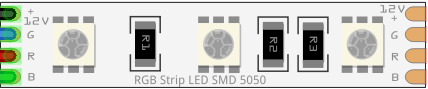
Pin Configuration
The 12V RGB LED strip typically has four pins or wires for connection. The pin configuration is as follows:
| Pin/Wire | Description |
|---|---|
| 12V | Positive voltage input (common anode) |
| R | Red channel (negative terminal for red LEDs) |
| G | Green channel (negative terminal for green LEDs) |
| B | Blue channel (negative terminal for blue LEDs) |
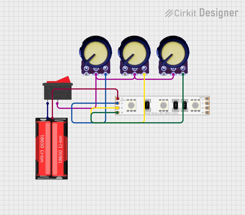
Usage Instructions
Connecting the 12V RGB LED Strip
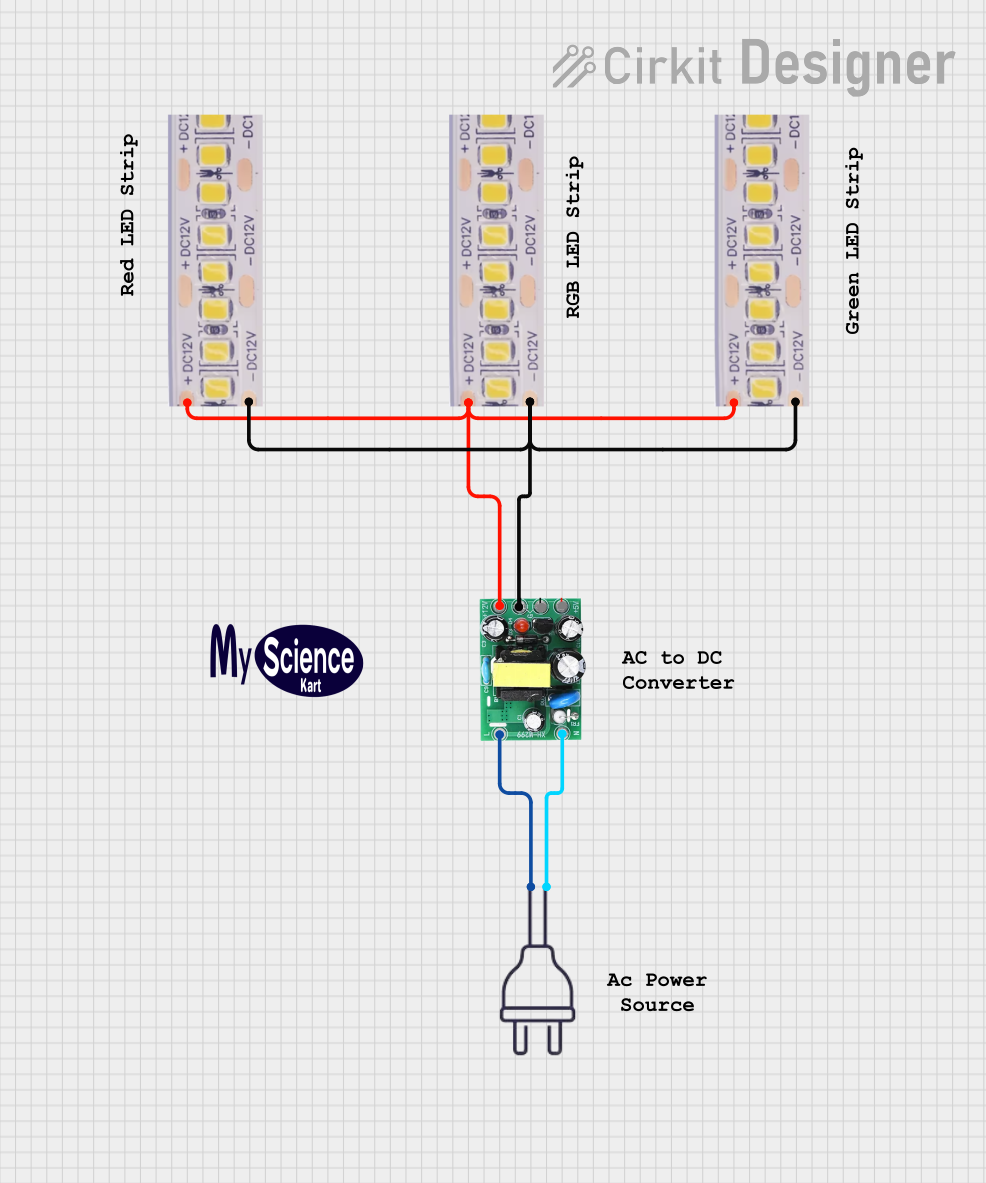
- Power Supply: Use a 12V DC power supply with sufficient current capacity. For example, a 5-meter strip with 60 LEDs per meter will require approximately 6A (14.4W/m × 5m ÷ 12V = 6A).
- Controller: Connect the LED strip to an RGB controller or microcontroller (e.g., Arduino) to control the colors and brightness. Ensure the controller supports common-anode RGB strips.
- Wiring:
- Connect the 12V pin of the strip to the positive terminal of the power supply.
- Connect the R, G, and B pins to the corresponding outputs of the controller or to MOSFETs for PWM control.
- Cutting the Strip: If needed, cut the strip at the marked cut points (usually every 3 LEDs). Ensure the cut section is properly insulated to prevent short circuits.
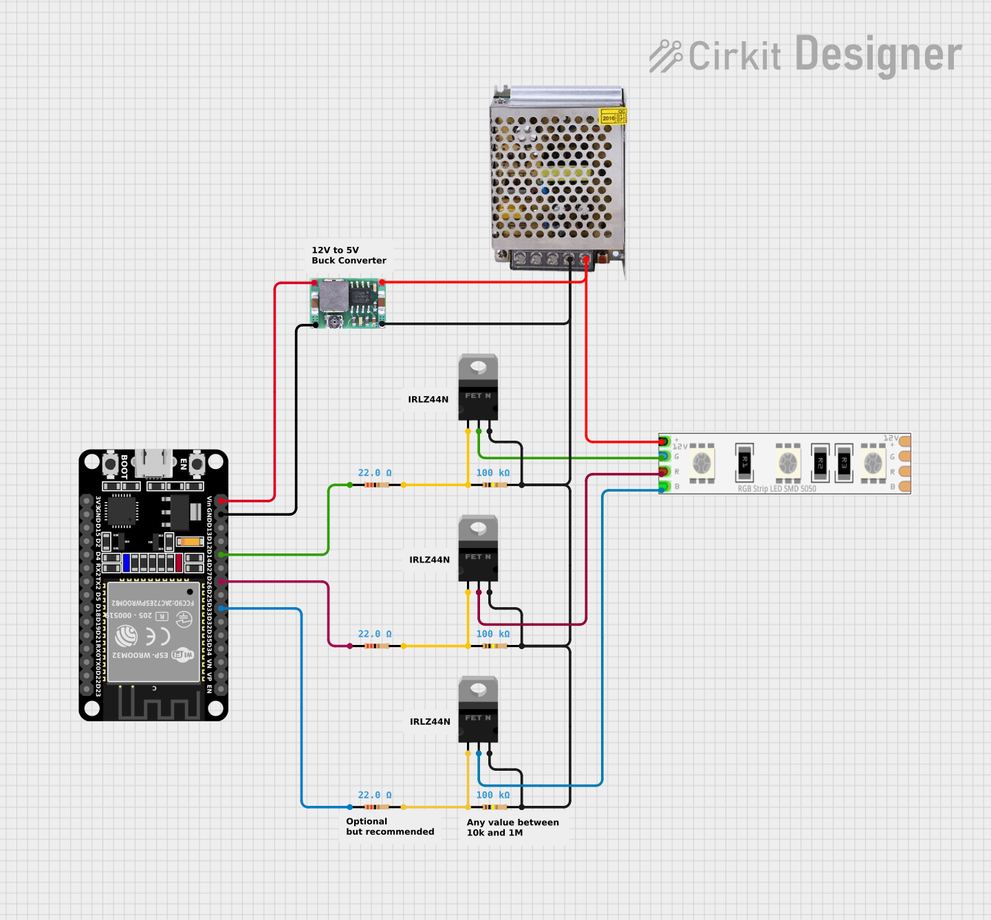
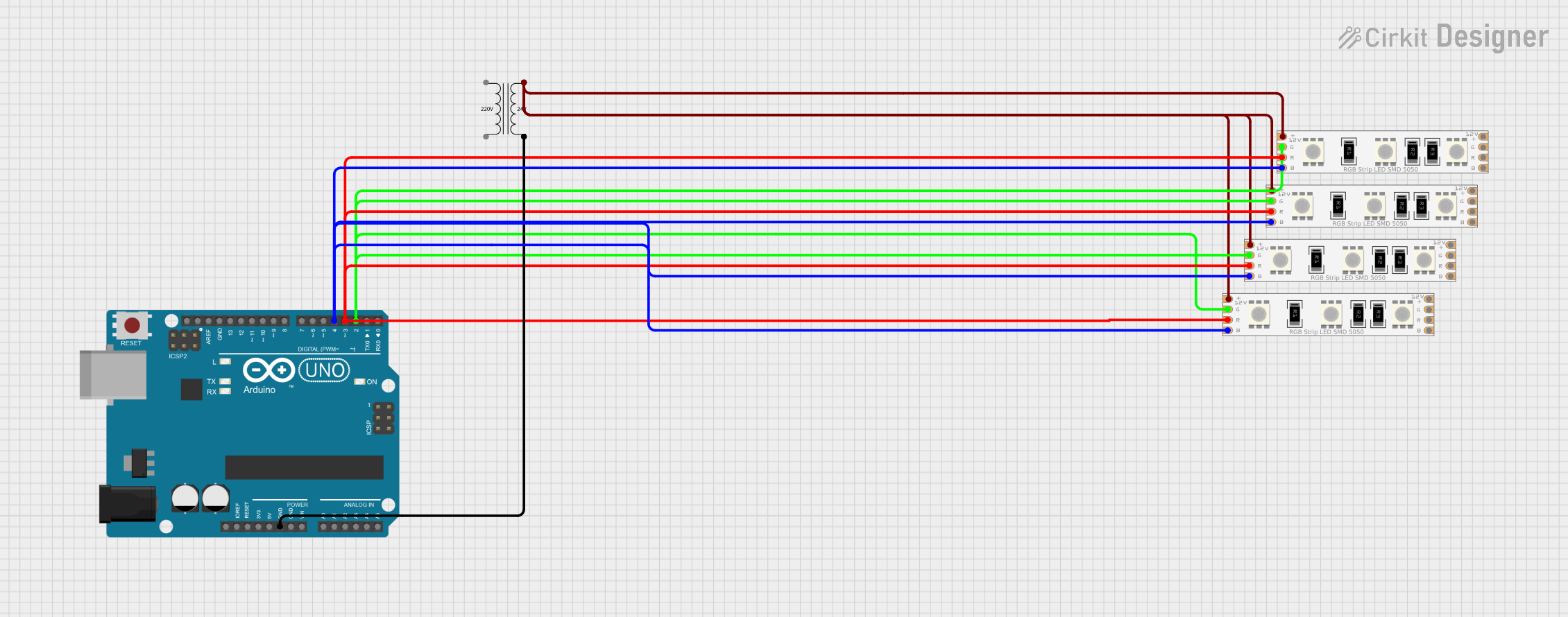
Example: Controlling with Arduino UNO
To control the 12V RGB LED strip with an Arduino UNO, you will need three N-channel MOSFETs (e.g., IRF540N) to handle the current. Below is an example circuit and code:
Circuit Diagram
- Connect the 12V pin of the LED strip to the positive terminal of a 12V power supply.
- Connect the R, G, and B pins of the strip to the drain terminals of three MOSFETs.
- Connect the source terminals of the MOSFETs to the ground of the power supply.
- Connect the gate terminals of the MOSFETs to Arduino PWM pins (e.g., pins 9, 10, and 11) through 220-ohm resistors.
- Connect the ground of the Arduino to the ground of the power supply.
Arduino Code
// Define PWM pins for RGB channels
const int redPin = 9;   // Red channel connected to pin 9
const int greenPin = 10; // Green channel connected to pin 10
const int bluePin = 11;  // Blue channel connected to pin 11

void setup() {
  // Set RGB pins as output
  pinMode(redPin, OUTPUT);
  pinMode(greenPin, OUTPUT);
  pinMode(bluePin, OUTPUT);
}

void loop() {
  // Example: Fade through red, green, and blue colors
  for (int i = 0; i <= 255; i++) {
    analogWrite(redPin, i);   // Increase red intensity
    analogWrite(greenPin, 255 - i); // Decrease green intensity
    analogWrite(bluePin, 0);  // Keep blue off
    delay(10); // Small delay for smooth fading
  }
}
Best Practices
- Use a power supply with at least 20% more current capacity than the calculated requirement to ensure reliable operation.
- Avoid bending the strip at sharp angles to prevent damage to the PCB and LEDs.
- If using a waterproof strip, ensure the ends are properly sealed after cutting to maintain waterproofing.
- Use appropriate heat sinks or ventilation if the strip is used at full brightness for extended periods.
Troubleshooting and FAQs
Common Issues and Solutions
LEDs not lighting up:
- Check the power supply voltage and current rating.
- Ensure all connections are secure and polarity is correct.
- Verify that the controller or Arduino is functioning properly.
Incorrect colors or dim output:
- Check for loose or damaged connections on the R, G, or B pins.
- Ensure the MOSFETs or controller outputs are functioning correctly.
- Verify that the power supply is not overloaded.
Flickering LEDs:
- Check for insufficient power supply capacity or voltage drops.
- Use thicker wires for long strips to reduce resistance.
- Add a capacitor (e.g., 1000µF) across the power supply terminals to stabilize voltage.
Overheating:
- Ensure the strip is not enclosed in a poorly ventilated space.
- Reduce brightness or use a heat sink if necessary.
FAQs
Q: Can I connect multiple strips together?
A: Yes, but ensure the power supply can handle the total current draw. For long runs, use power injection at intervals to prevent voltage drops.
Q: How do I control individual LEDs on the strip?
A: The 12V RGB LED strip does not support individual LED control. For this functionality, use addressable LED strips like WS2812B or APA102.
Q: Can I use a 5V power supply?
A: No, the strip is designed for 12V operation. Using a lower voltage will result in dim or non-functional LEDs.
Q: Is the strip safe to use outdoors?
A: Only waterproof versions (IP65 or higher) are suitable for outdoor use. Ensure all connections are weatherproofed.