How to Use DRV8825 : Examples, Pinouts, and Specs
Introduction
The DRV8825 is a stepper motor driver designed to control bipolar stepper motors with precision and efficiency. Manufactured by Arduino, this component (Part ID: Stepper Motor Driver) supports microstepping, allowing for smoother and more accurate motor movements. It features adjustable current control, over-temperature protection, and a wide operating voltage range, making it a versatile choice for robotics, 3D printers, CNC machines, and other automation systems.
Explore Projects Built with DRV8825
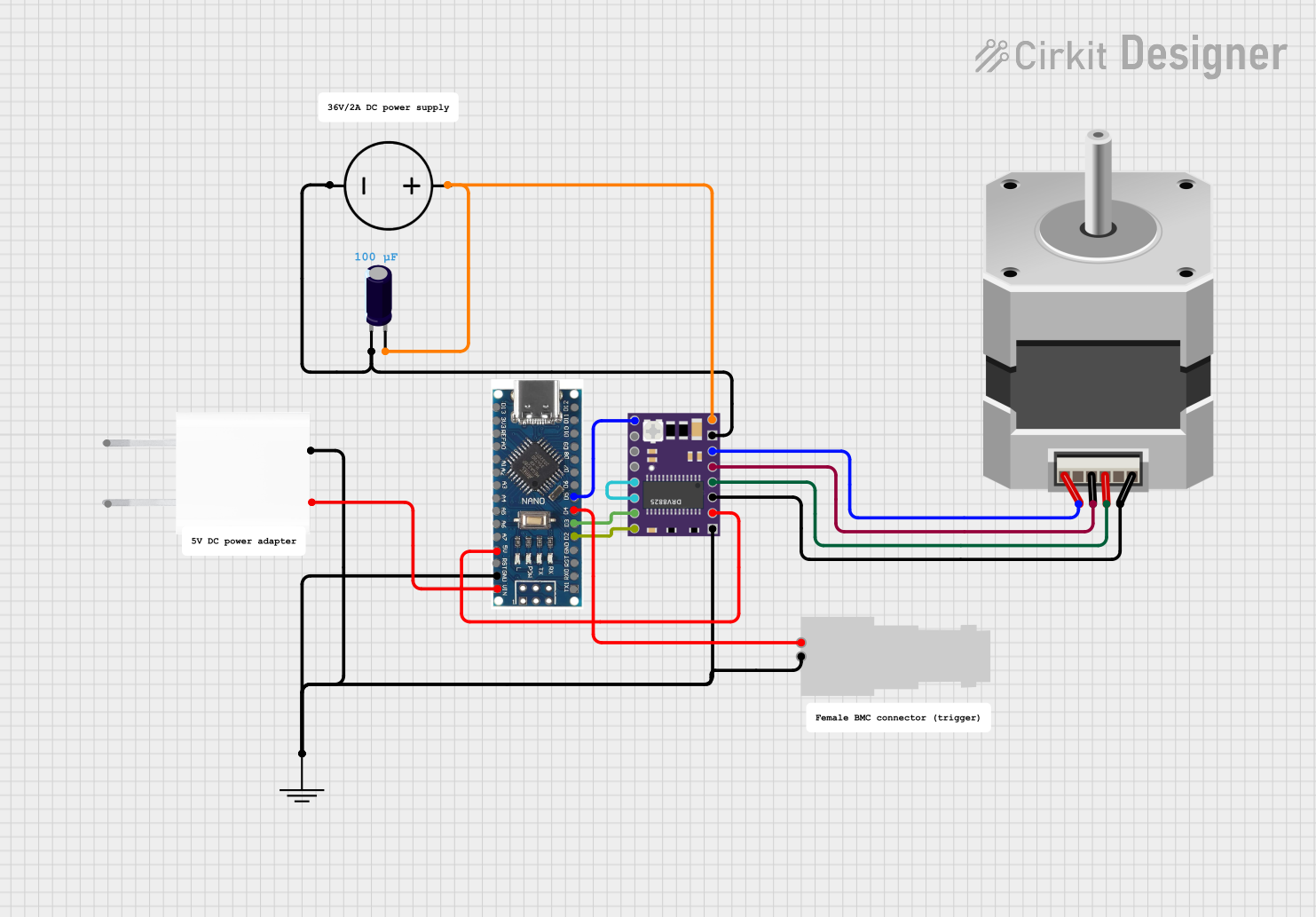
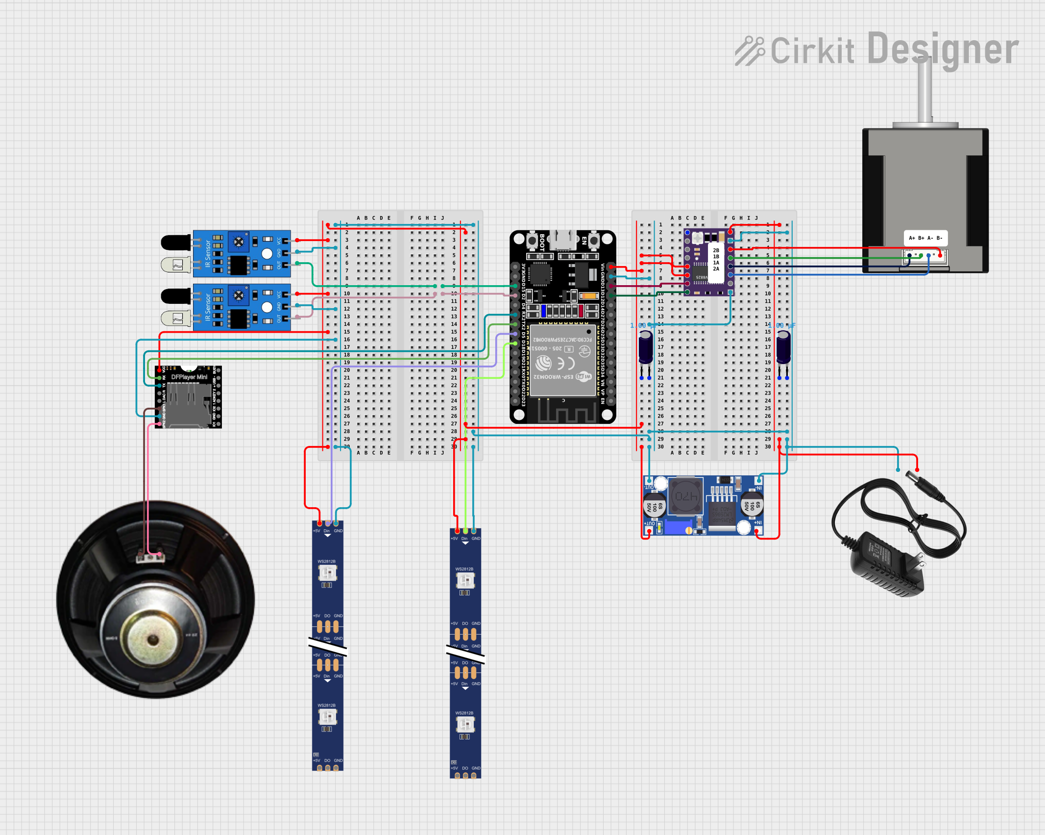

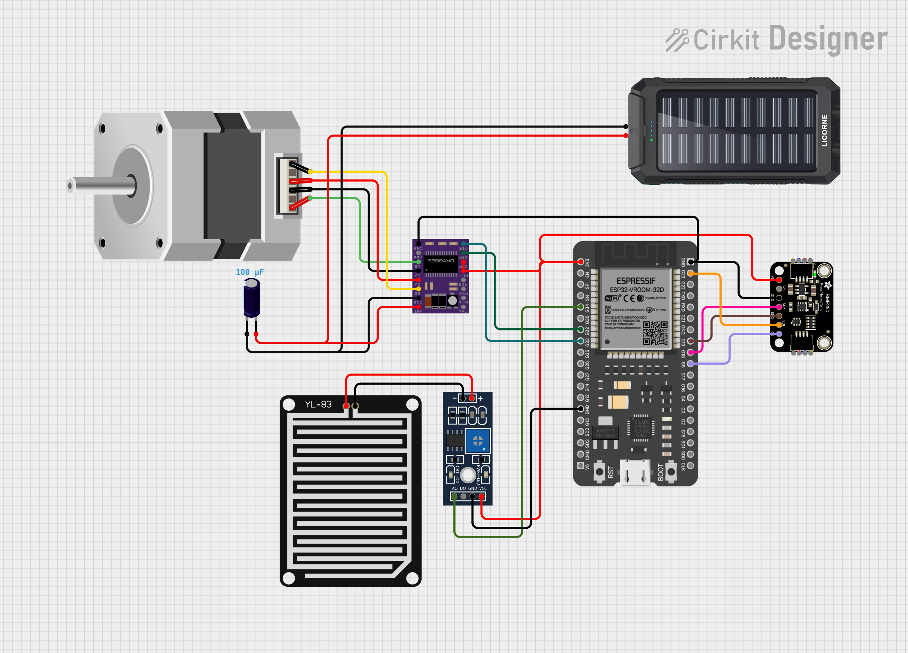
Explore Projects Built with DRV8825
Common Applications:
- Robotics and automation systems
- 3D printers and CNC machines
- Camera sliders and gimbals
- Precision positioning systems
Technical Specifications
Key Technical Details:
- Operating Voltage Range: 8.2V to 45V
- Maximum Output Current: 2.2A per coil (with sufficient cooling)
- Microstepping Modes: Full-step, 1/2, 1/4, 1/8, 1/16, and 1/32 steps
- Logic Voltage: 3.3V or 5V compatible
- Over-Temperature Protection: Yes
- Over-Current Protection: Yes
- Adjustable Current Control: Yes (via potentiometer)
- Dimensions: 15mm x 20mm (approx.)
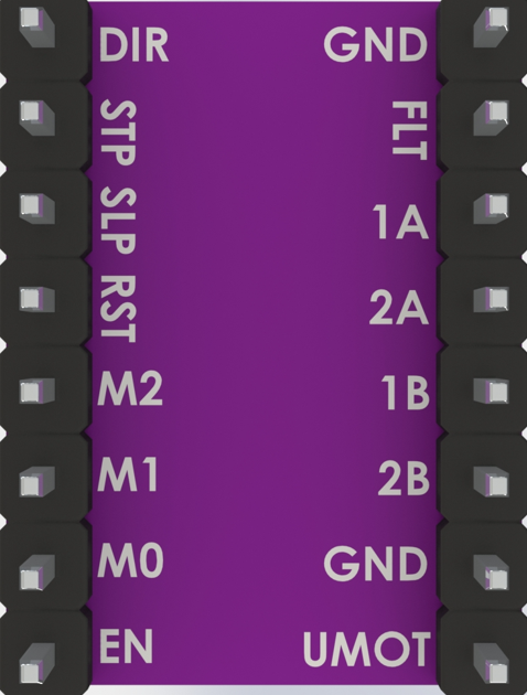
Pin Configuration and Descriptions:
The DRV8825 module has 16 pins. Below is the pinout and description:
| Pin Name | Type | Description |
|---|---|---|
| VMOT | Power Input | Motor power supply (8.2V to 45V). Connect a capacitor (e.g., 100µF) across VMOT and GND. |
| GND | Power Ground | Ground connection for motor power supply. |
| VDD | Power Input | Logic power supply (3.3V or 5V). |
| GND | Power Ground | Ground connection for logic power supply. |
| STEP | Input | Step signal input. Each pulse moves the motor one step. |
| DIR | Input | Direction control input. High or low determines motor rotation direction. |
| ENABLE | Input | Enable/disable the driver. Low = enabled, High = disabled. |
| MS1, MS2, MS3 | Input | Microstepping mode selection pins. |
| RESET | Input | Resets the driver. Active low. |
| SLEEP | Input | Puts the driver into low-power sleep mode. Active low. |
| OUT1A, OUT1B | Output | Outputs for motor coil 1. |
| OUT2A, OUT2B | Output | Outputs for motor coil 2. |
| FAULT | Output | Fault indicator. Low when a fault condition occurs (e.g., over-temperature). |
Microstepping Mode Selection:
The microstepping mode is configured using the MS1, MS2, and MS3 pins as shown below:
| MS1 | MS2 | MS3 | Microstepping Mode |
|---|---|---|---|
| Low | Low | Low | Full Step |
| High | Low | Low | 1/2 Step |
| Low | High | Low | 1/4 Step |
| High | High | Low | 1/8 Step |
| Low | Low | High | 1/16 Step |
| High | High | High | 1/32 Step |
Usage Instructions
How to Use the DRV8825 in a Circuit:
Power Connections:
- Connect the motor power supply to the VMOT and GND pins. Use a capacitor (e.g., 100µF) across these pins to reduce voltage spikes.
- Connect the logic power supply (3.3V or 5V) to the VDD and GND pins.
Motor Connections:
- Connect the two coils of the stepper motor to the OUT1A, OUT1B, OUT2A, and OUT2B pins. Ensure the correct pairing of motor wires.
Control Signals:
- Connect the STEP and DIR pins to your microcontroller (e.g., Arduino UNO). Use digital pins to send step pulses and direction signals.
- Optionally, connect the ENABLE pin to control driver activation.
Microstepping Configuration:
- Set the MS1, MS2, and MS3 pins to the desired logic levels for the required microstepping mode.
Adjusting Current Limit:
- Use the onboard potentiometer to set the current limit. Measure the voltage on the "REF" pin and calculate the current limit using the formula:
(For example, if VREF = 0.5V, the current limit is 1A.)Current Limit = VREF × 2
- Use the onboard potentiometer to set the current limit. Measure the voltage on the "REF" pin and calculate the current limit using the formula:
Optional Connections:
- Connect the RESET and SLEEP pins to logic HIGH to enable normal operation.
- Monitor the FAULT pin for error conditions.
Example Arduino Code:
Below is an example of how to control a stepper motor using the DRV8825 and an Arduino UNO:
// Define pin connections
#define STEP_PIN 3  // Pin connected to STEP
#define DIR_PIN 4   // Pin connected to DIR

void setup() {
  pinMode(STEP_PIN, OUTPUT); // Set STEP pin as output
  pinMode(DIR_PIN, OUTPUT);  // Set DIR pin as output

  digitalWrite(DIR_PIN, HIGH); // Set initial direction (HIGH = clockwise)
}

void loop() {
  // Generate step pulses
  digitalWrite(STEP_PIN, HIGH); // Set STEP pin HIGH
  delayMicroseconds(500);       // Wait 500 microseconds
  digitalWrite(STEP_PIN, LOW);  // Set STEP pin LOW
  delayMicroseconds(500);       // Wait 500 microseconds
}
Important Considerations:
- Ensure the motor power supply voltage is within the specified range (8.2V to 45V).
- Use a heatsink or cooling fan if operating at high currents to prevent overheating.
- Avoid connecting or disconnecting the motor while the driver is powered to prevent damage.
- Always set the current limit to match your motor's rated current to avoid overloading.
Troubleshooting and FAQs
Common Issues and Solutions:
Motor Not Moving:
- Cause: Incorrect wiring or insufficient power supply.
- Solution: Double-check motor connections and ensure the power supply meets voltage and current requirements.
Driver Overheating:
- Cause: Current limit set too high or inadequate cooling.
- Solution: Adjust the current limit using the potentiometer and add a heatsink or cooling fan.
Erratic Motor Movement:
- Cause: Noise on control signals or incorrect microstepping configuration.
- Solution: Use pull-down resistors on control pins and verify MS1, MS2, and MS3 settings.
FAULT Pin Active (Low):
- Cause: Over-temperature or over-current condition.
- Solution: Reduce the current limit and ensure proper cooling.
Motor Vibrates but Does Not Rotate:
- Cause: Incorrect stepper motor wiring.
- Solution: Verify the correct pairing of motor wires and reconnect.
FAQs:
Q: Can the DRV8825 drive unipolar stepper motors?
A: No, the DRV8825 is designed for bipolar stepper motors only.Q: What is the maximum step pulse frequency?
A: The DRV8825 can handle step pulse frequencies up to 250kHz.Q: Can I use the DRV8825 with a 12V power supply?
A: Yes, the DRV8825 supports power supply voltages from 8.2V to 45V.Q: How do I calculate the current limit for my motor?
A: Measure the VREF voltage and use the formula:Current Limit = VREF × 2.
By following this documentation, you can effectively use the DRV8825 stepper motor driver in your projects!