How to Use L293D: Examples, Pinouts, and Specs
Introduction
The L293D is a quadruple high-current half-H driver designed to control the direction and speed of DC motors and stepper motors. Manufactured by Generic, this versatile IC can drive two motors simultaneously, making it ideal for robotics and motor control applications. The L293D features built-in diodes for back EMF protection, ensuring safe operation when driving inductive loads like motors.
Explore Projects Built with L293D
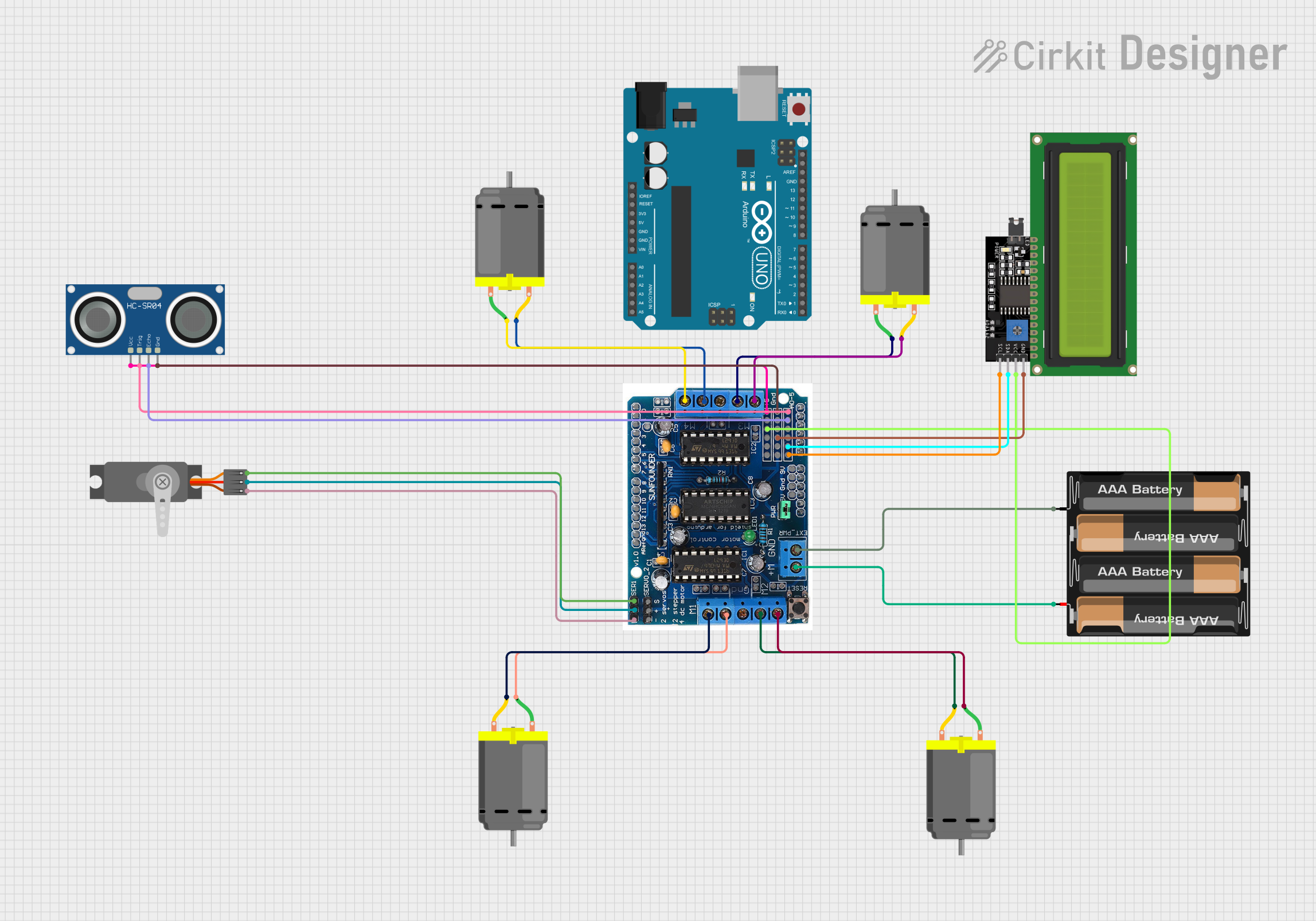

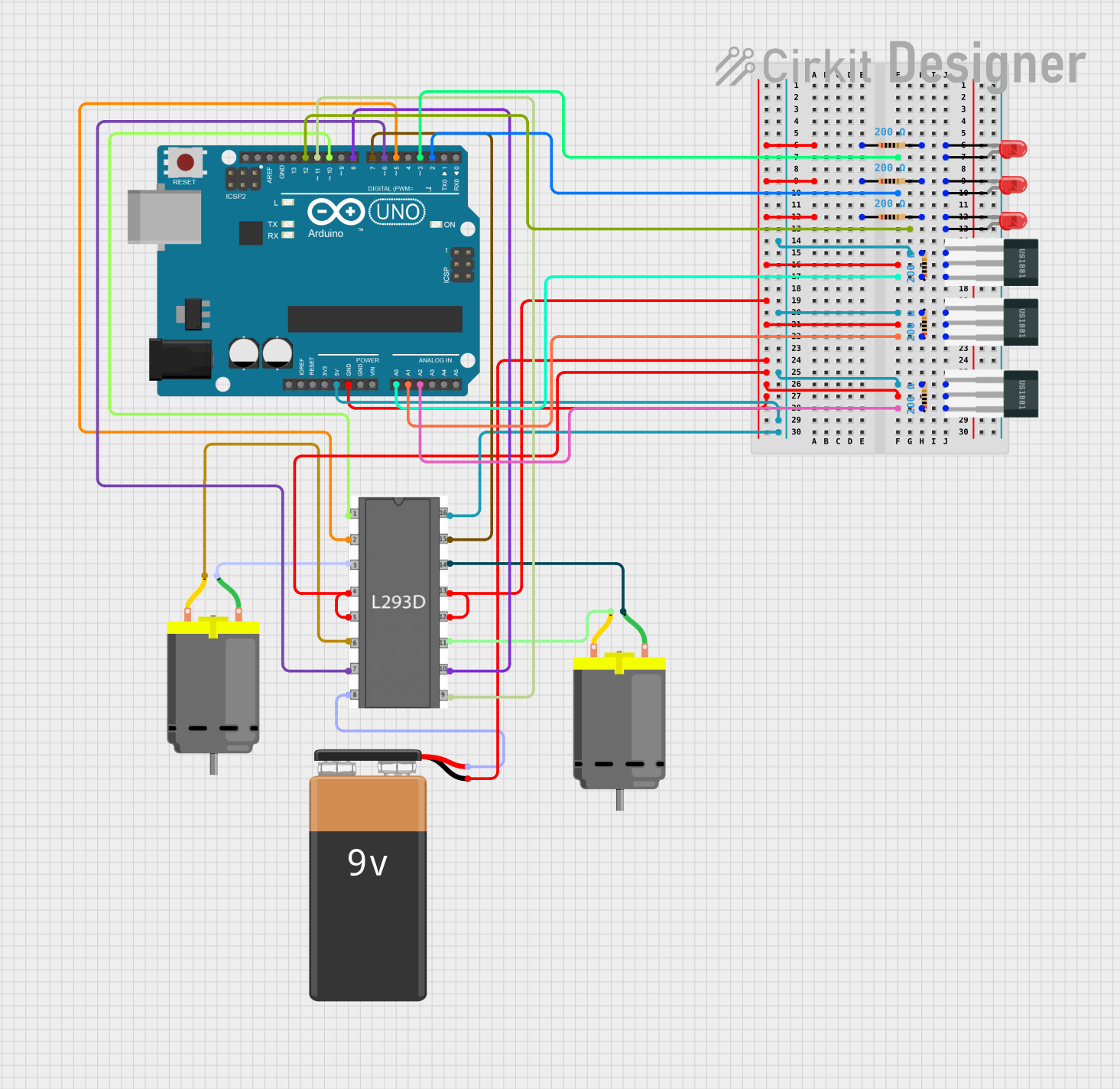
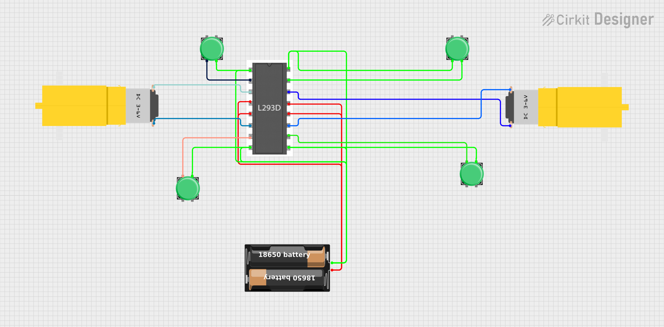
Explore Projects Built with L293D
Common Applications
- Robotics and automation systems
- Motorized toys and vehicles
- Stepper motor control for CNC machines and 3D printers
- Conveyor belt systems
- Home automation projects
Technical Specifications
The L293D is a robust motor driver IC with the following key specifications:
| Parameter | Value |
|---|---|
| Manufacturer Part ID | L293D |
| Operating Voltage Range | 4.5V to 36V |
| Logic Input Voltage Range | 0V to 7V |
| Maximum Output Current | 600mA per channel (1.2A peak) |
| Number of Channels | 2 (can drive 2 DC motors or 1 stepper motor) |
| Built-in Protection | Back EMF diodes |
| Operating Temperature Range | -25°C to 150°C |
| Package Type | 16-pin DIP or SOIC |
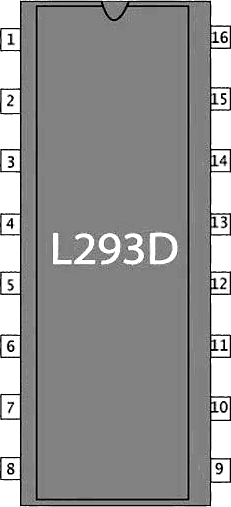
Pin Configuration and Descriptions
The L293D has 16 pins, as described in the table below:
| Pin Number | Pin Name | Description |
|---|---|---|
| 1 | Enable 1,2 | Enables the first motor driver (pins 3 and 6). Active HIGH. |
| 2 | Input 1 | Logic input for controlling the direction of Motor 1. |
| 3 | Output 1 | Output for Motor 1. Connect to one terminal of the motor. |
| 4 | Ground (GND) | Ground connection. |
| 5 | Ground (GND) | Ground connection. |
| 6 | Output 2 | Output for Motor 1. Connect to the other terminal of the motor. |
| 7 | Input 2 | Logic input for controlling the direction of Motor 1. |
| 8 | Vcc2 (Motor Vcc) | Supply voltage for the motors (4.5V to 36V). |
| 9 | Enable 3,4 | Enables the second motor driver (pins 11 and 14). Active HIGH. |
| 10 | Input 3 | Logic input for controlling the direction of Motor 2. |
| 11 | Output 3 | Output for Motor 2. Connect to one terminal of the motor. |
| 12 | Ground (GND) | Ground connection. |
| 13 | Ground (GND) | Ground connection. |
| 14 | Output 4 | Output for Motor 2. Connect to the other terminal of the motor. |
| 15 | Input 4 | Logic input for controlling the direction of Motor 2. |
| 16 | Vcc1 (Logic Vcc) | Supply voltage for the logic circuitry (5V). |
Usage Instructions
The L293D is straightforward to use in motor control circuits. Below are the steps and considerations for using the IC effectively:
Connecting the L293D
Power Supply:
- Connect Vcc1 (Pin 16) to a 5V power source for the logic circuitry.
- Connect Vcc2 (Pin 8) to the motor power supply (4.5V to 36V, depending on the motor's requirements).
- Connect all GND pins (Pins 4, 5, 12, 13) to the ground of the power supply.
Motor Connections:
- Connect the motor terminals to the output pins (e.g., Motor 1 to Pins 3 and 6, Motor 2 to Pins 11 and 14).
Control Inputs:
- Use the input pins (e.g., Input 1 and Input 2 for Motor 1) to control the motor's direction.
- Enable the motor driver by setting the corresponding enable pin (e.g., Enable 1,2 for Motor 1) HIGH.
Logic Control:
- Use a microcontroller (e.g., Arduino UNO) or other logic circuits to send HIGH/LOW signals to the input pins.
Example: Controlling a DC Motor with Arduino UNO
Below is an example Arduino sketch to control a DC motor using the L293D:
// Define L293D pins connected to Arduino
const int enablePin = 9;  // Enable pin for Motor 1 (connected to Pin 1 of L293D)
const int input1 = 7;     // Input 1 for Motor 1 (connected to Pin 2 of L293D)
const int input2 = 8;     // Input 2 for Motor 1 (connected to Pin 7 of L293D)

void setup() {
  // Set pin modes
  pinMode(enablePin, OUTPUT);
  pinMode(input1, OUTPUT);
  pinMode(input2, OUTPUT);

  // Initialize motor in stopped state
  digitalWrite(enablePin, LOW);  // Disable motor
  digitalWrite(input1, LOW);     // Set direction to LOW
  digitalWrite(input2, LOW);     // Set direction to LOW
}

void loop() {
  // Rotate motor in one direction
  digitalWrite(enablePin, HIGH); // Enable motor
  digitalWrite(input1, HIGH);    // Set direction
  digitalWrite(input2, LOW);     // Set opposite direction
  delay(2000);                   // Run for 2 seconds

  // Stop motor
  digitalWrite(enablePin, LOW);  // Disable motor
  delay(1000);                   // Wait for 1 second

  // Rotate motor in the opposite direction
  digitalWrite(enablePin, HIGH); // Enable motor
  digitalWrite(input1, LOW);     // Set opposite direction
  digitalWrite(input2, HIGH);    // Set direction
  delay(2000);                   // Run for 2 seconds

  // Stop motor
  digitalWrite(enablePin, LOW);  // Disable motor
  delay(1000);                   // Wait for 1 second
}
Best Practices
- Always use a decoupling capacitor (e.g., 100µF) across the motor power supply to reduce noise.
- Ensure the motor's current does not exceed the L293D's maximum rating (600mA per channel).
- Use heat sinks or proper ventilation if the IC gets too hot during operation.
- For higher current requirements, consider using external transistors or MOSFETs.
Troubleshooting and FAQs
Common Issues
Motor Not Spinning:
- Check if the enable pin is set HIGH.
- Verify the input pin logic levels.
- Ensure the motor power supply (Vcc2) is connected and within the specified range.
Overheating:
- Ensure the motor's current does not exceed 600mA per channel.
- Use a heat sink or reduce the load on the motor.
Erratic Motor Behavior:
- Check for loose connections or poor soldering.
- Add a decoupling capacitor across the motor power supply.
Arduino Not Controlling the Motor:
- Verify the connections between the Arduino and the L293D.
- Ensure the Arduino pins are configured as outputs in the code.
FAQs
Q: Can the L293D drive stepper motors?
A: Yes, the L293D can drive a unipolar or bipolar stepper motor by controlling the sequence of inputs to the motor windings.
Q: What is the difference between Vcc1 and Vcc2?
A: Vcc1 powers the logic circuitry (typically 5V), while Vcc2 powers the motors (4.5V to 36V).
Q: Can I use the L293D with a 3.3V microcontroller?
A: The L293D requires a minimum logic voltage of 4.5V, so it is not directly compatible with 3.3V logic. Use a level shifter or a 5V microcontroller.
Q: How do I protect the IC from back EMF?
A: The L293D has built-in diodes for back EMF protection, so no additional components are required.