How to Use SX1308: Examples, Pinouts, and Specs
Introduction
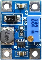
The SX1308 is a highly integrated step-up boost converter designed by Shenzhen Suosemi Tech. It is widely used in applications requiring efficient voltage step-up from a lower input voltage to a higher output voltage. The SX1308 is compact, cost-effective, and highly efficient, making it suitable for powering devices in battery-operated systems, portable electronics, and IoT applications.
Explore Projects Built with SX1308


Explore Projects Built with SX1308
Common Applications and Use Cases
- Powering microcontrollers and sensors in IoT devices
- Boosting voltage for LED strips and displays
- Battery-powered devices requiring higher operating voltages
- Portable electronics such as handheld gadgets and wearables
Technical Specifications
Key Technical Details
- Input Voltage Range: 2V to 24V
- Output Voltage Range: 2V to 28V
- Switching Frequency: 1.2 MHz
- Maximum Output Current: 2A (depending on input voltage and load conditions)
- Efficiency: Up to 95%
- Quiescent Current: < 120 µA
- Operating Temperature Range: -40°C to +85°C
- Package Type: SOT-23-6
Pin Configuration and Descriptions
The SX1308 is typically available in a 6-pin SOT-23 package. Below is the pinout and description:
| Pin Number | Pin Name | Description |
|---|---|---|
| 1 | SW | Switching node. Connect to the inductor and diode. |
| 2 | GND | Ground pin. Connect to the system ground. |
| 3 | FB | Feedback pin. Connect to a resistor divider to set the output voltage. |
| 4 | EN | Enable pin. Drive high to enable the converter, low to disable it. |
| 5 | VIN | Input voltage pin. Connect to the input power source. |
| 6 | VOUT | Output voltage pin. Connect to the load and output capacitor. |
Usage Instructions
How to Use the SX1308 in a Circuit
Input and Output Capacitors:
- Place a low-ESR capacitor (e.g., 10 µF ceramic) close to the VIN pin to stabilize the input voltage.
- Use a similar capacitor at the VOUT pin to smooth the output voltage.
Inductor Selection:
- Choose an inductor with a suitable current rating (e.g., 2A or higher) and an inductance value between 4.7 µH and 22 µH, depending on the desired output voltage and current.
Feedback Resistor Divider:
- Use two resistors to set the output voltage. The formula is: [ V_{OUT} = V_{REF} \times \left(1 + \frac{R1}{R2}\right) ] where ( V_{REF} ) is typically 0.6V.
Enable Pin:
- Connect the EN pin to VIN or a microcontroller GPIO pin to control the converter's operation.
Diode Selection:
- Use a Schottky diode with a low forward voltage drop and a current rating higher than the maximum output current.
Important Considerations and Best Practices
- Ensure proper PCB layout to minimize noise and improve efficiency. Place components as close to the IC as possible.
- Avoid exceeding the maximum input voltage (24V) or output voltage (28V) to prevent damage.
- Use a heat sink or proper ventilation if operating at high currents to manage thermal dissipation.
- For applications requiring precise output voltage, use resistors with a low tolerance (e.g., 1%).
Example: Connecting the SX1308 to an Arduino UNO
The SX1308 can be used to power an Arduino UNO from a lower voltage source, such as a 3.7V Li-ion battery. Below is an example circuit and Arduino code to enable/disable the SX1308 using a GPIO pin.
Circuit Diagram
- Connect the battery's positive terminal to the VIN pin of the SX1308.
- Connect the VOUT pin to the Arduino's 5V pin.
- Connect the EN pin to an Arduino GPIO pin (e.g., D7) for control.
Arduino Code
// Define the pin connected to the SX1308 EN pin
const int enablePin = 7;

void setup() {
  // Set the enable pin as an output
  pinMode(enablePin, OUTPUT);

  // Enable the SX1308 by setting the pin HIGH
  digitalWrite(enablePin, HIGH);
}

void loop() {
  // Example: Toggle the SX1308 on and off every 5 seconds
  digitalWrite(enablePin, HIGH); // Enable the SX1308
  delay(5000);                   // Wait for 5 seconds
  digitalWrite(enablePin, LOW);  // Disable the SX1308
  delay(5000);                   // Wait for 5 seconds
}
Troubleshooting and FAQs
Common Issues and Solutions
No Output Voltage:
- Check the input voltage and ensure it is within the specified range (2V to 24V).
- Verify that the EN pin is pulled high to enable the converter.
- Inspect the feedback resistor divider for correct values and connections.
Output Voltage is Unstable:
- Ensure proper placement of input and output capacitors close to the IC.
- Check the inductor value and ensure it is appropriate for the load conditions.
- Verify that the load current does not exceed the maximum rating.
Excessive Heat:
- Ensure the input and output voltages are within the specified range.
- Use an inductor and diode with sufficient current ratings.
- Improve PCB layout to enhance heat dissipation.
Low Efficiency:
- Use low-ESR capacitors and a Schottky diode to minimize losses.
- Optimize the feedback resistor values for the desired output voltage.
FAQs
Q1: Can the SX1308 be used to power a 12V LED strip from a 5V source?
A1: Yes, the SX1308 can step up a 5V input to 12V, provided the current requirements of the LED strip do not exceed the SX1308's maximum output current.
Q2: What happens if the input voltage drops below 2V?
A2: The SX1308 will stop operating, and the output voltage will drop. Ensure the input voltage remains within the specified range.
Q3: Can I use the SX1308 for audio applications?
A3: While the SX1308 is not specifically designed for audio, it can be used in low-power audio circuits. However, ensure proper filtering to minimize noise.
Q4: How do I calculate the inductor value for my application?
A4: Refer to the SX1308 datasheet for detailed formulas and guidelines based on your input voltage, output voltage, and load current requirements.