How to Use Adafruit MiniBoost 5V 100mA Charge Pump AP3602A: Examples, Pinouts, and Specs
Introduction
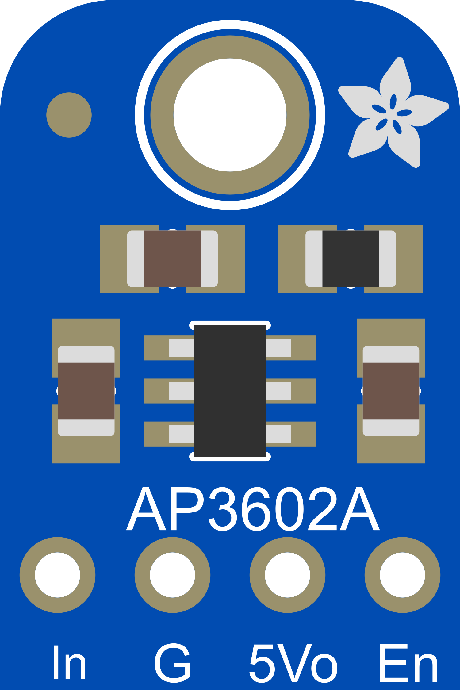
The Adafruit MiniBoost 5V 100mA Charge Pump AP3602A is a compact and efficient voltage booster designed to step up lower input voltages to a stable 5V output. It is capable of delivering up to 100mA of output current, making it ideal for powering low-power devices such as microcontrollers, sensors, and small electronic modules. Its small size and simplicity make it a popular choice for portable and battery-powered applications.
Explore Projects Built with Adafruit MiniBoost 5V 100mA Charge Pump AP3602A
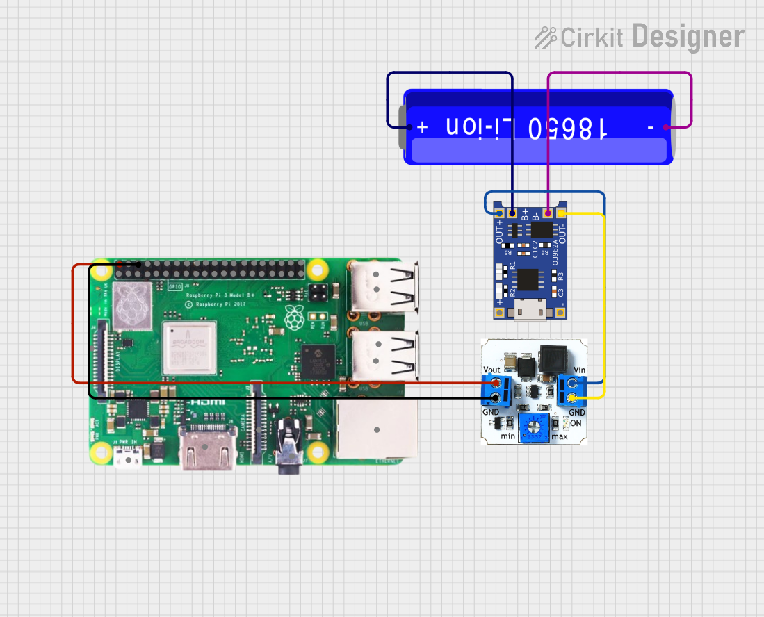


Explore Projects Built with Adafruit MiniBoost 5V 100mA Charge Pump AP3602A
Common Applications and Use Cases
- Powering 5V microcontrollers (e.g., Arduino, ESP8266) from lower voltage sources.
- Boosting voltage from single-cell lithium-ion/polymer batteries.
- Driving low-power sensors and modules in portable devices.
- Applications requiring a compact and efficient 5V power source.
Technical Specifications
Key Technical Details
- Input Voltage Range: 2.7V to 4.5V
- Output Voltage: 5V (regulated)
- Maximum Output Current: 100mA
- Efficiency: Up to 85% (depending on load and input voltage)
- Quiescent Current: ~120µA (typical)
- Switching Frequency: 1MHz
- Operating Temperature Range: -40°C to +85°C
- Package: SOT23-6 (surface-mount)
Pin Configuration and Descriptions
The Adafruit MiniBoost AP3602A has six pins, as described in the table below:
| Pin Name | Pin Number | Description |
|---|---|---|
| VIN | 1 | Input voltage pin. Connect to the power source (2.7V to 4.5V). |
| GND | 2 | Ground pin. Connect to the ground of the circuit. |
| VOUT | 3 | Regulated 5V output pin. Connect to the load requiring 5V. |
| EN | 4 | Enable pin. Drive high to enable the output; drive low to disable the output. |
| FB | 5 | Feedback pin. Internally connected for fixed 5V output; no external connection needed. |
| NC | 6 | No connection. Leave this pin unconnected. |
Usage Instructions
How to Use the Component in a Circuit
- Power Input: Connect the VIN pin to a power source with a voltage between 2.7V and 4.5V. This could be a single-cell LiPo battery or a 3.3V power supply.
- Ground Connection: Connect the GND pin to the ground of your circuit.
- Output Voltage: Connect the VOUT pin to the device or circuit that requires a 5V power supply. Ensure the load does not exceed 100mA.
- Enable Pin: To enable the output, connect the EN pin to VIN or a logic high signal. To disable the output, connect the EN pin to GND or a logic low signal.
- Bypass Capacitors: Place a 1µF ceramic capacitor close to the VIN pin and a 10µF ceramic capacitor close to the VOUT pin for stable operation.
Important Considerations and Best Practices
- Load Current: Ensure the total load current does not exceed 100mA to prevent overheating or instability.
- Input Voltage: Do not exceed the maximum input voltage of 4.5V to avoid damaging the component.
- Thermal Management: Although the AP3602A is efficient, ensure adequate ventilation or heat dissipation in high-temperature environments.
- PCB Layout: Keep the input and output capacitors as close as possible to the VIN and VOUT pins to minimize noise and improve stability.
Example: Using with an Arduino UNO
The Adafruit MiniBoost can be used to power an Arduino UNO from a 3.3V source. Below is an example circuit and Arduino code to toggle the EN pin.
Circuit Connections
- Connect the VIN pin to a 3.3V power source.
- Connect the GND pin to the Arduino's GND.
- Connect the VOUT pin to the Arduino's 5V pin.
- Connect the EN pin to an Arduino digital pin (e.g., D7).
Arduino Code
// Example code to control the EN pin of the Adafruit MiniBoost AP3602A
// This code toggles the EN pin to enable and disable the 5V output.

#define EN_PIN 7  // Define the Arduino pin connected to the EN pin

void setup() {
  pinMode(EN_PIN, OUTPUT);  // Set EN_PIN as an output
  digitalWrite(EN_PIN, LOW);  // Start with the 5V output disabled
}

void loop() {
  digitalWrite(EN_PIN, HIGH);  // Enable the 5V output
  delay(5000);  // Keep the output enabled for 5 seconds

  digitalWrite(EN_PIN, LOW);  // Disable the 5V output
  delay(5000);  // Keep the output disabled for 5 seconds
}
Troubleshooting and FAQs
Common Issues and Solutions
No Output Voltage:
- Ensure the EN pin is connected to a logic high signal or VIN.
- Verify that the input voltage is within the specified range (2.7V to 4.5V).
- Check for proper connections and ensure the input and output capacitors are installed.
Output Voltage Drops Under Load:
- Ensure the load current does not exceed 100mA.
- Verify that the input power source can supply sufficient current.
Excessive Heat:
- Check for overloading conditions or input voltage exceeding 4.5V.
- Ensure proper ventilation or heat dissipation.
Noise or Instability:
- Ensure the input and output capacitors are placed close to the VIN and VOUT pins.
- Use low-ESR ceramic capacitors for best performance.
FAQs
Q: Can I use the AP3602A to power a device requiring more than 100mA?
A: No, the AP3602A is designed for a maximum output current of 100mA. Exceeding this limit may cause instability or damage the component.
Q: Can I use the AP3602A with a 5V input?
A: No, the input voltage must be between 2.7V and 4.5V. Using a 5V input will exceed the component's specifications and may cause damage.
Q: Is the output voltage adjustable?
A: No, the AP3602A provides a fixed 5V output and does not support adjustable output voltage.
Q: What type of capacitors should I use?
A: Use ceramic capacitors with low ESR. A 1µF capacitor for VIN and a 10µF capacitor for VOUT are recommended.