
How to Use 555 Timer: Examples, Pinouts, and Specs
 Design with 555 Timer in Cirkit Designer
Introduction
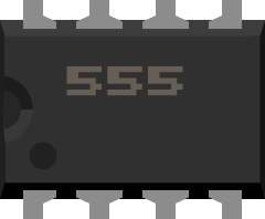
The 555 Timer is a highly versatile integrated circuit (IC) designed for generating precise timing and oscillation. Manufactured by Texas Instruments under the part ID NE555, this IC is widely used in electronics due to its simplicity, reliability, and flexibility. It can operate in three primary modes: astable, monostable, and bistable, making it suitable for a variety of applications.
Explore Projects Built with 555 Timer
 Open Project in Cirkit Designer
 Open Project in Cirkit Designer
 Open Project in Cirkit Designer
 Open Project in Cirkit Designer
Explore Projects Built with 555 Timer
Open Project in Cirkit DesignerOpen Project in Cirkit DesignerOpen Project in Cirkit DesignerOpen Project in Cirkit DesignerCommon Applications
- Pulse generation
- Frequency division
- Time delay circuits
- LED flashers
- PWM (Pulse Width Modulation) generation
- Oscillators and waveform generators
Technical Specifications
Below are the key technical details of the NE555 Timer:
| Parameter | Value |
|---|---|
| Supply Voltage (Vcc) | 4.5V to 16V |
| Supply Current (Vcc = 5V) | 3 mA (typical) |
| Output Current (Sink/Source) | 200 mA (maximum) |
| Operating Temperature Range | 0°C to 70°C |
| Timing Accuracy | ±1% |
| Maximum Frequency | 500 kHz |
| Package Type | PDIP, SOIC, TSSOP |
Pin Configuration and Descriptions
The NE555 Timer is an 8-pin IC. Below is the pinout and description:
| Pin Number | Pin Name | Description |
|---|---|---|
| 1 | GND | Ground pin. Connect to the negative terminal of the power supply. |
| 2 | TRIG | Trigger input. A low voltage (<1/3 Vcc) on this pin starts the timing cycle. |
| 3 | OUT | Output pin. Provides the output signal (high or low) based on the timer mode. |
| 4 | RESET | Reset pin. Active low. Pulling this pin low resets the timer. |
| 5 | CTRL | Control voltage. Used to adjust the threshold voltage (optional). |
| 6 | THR | Threshold input. Monitors the capacitor voltage to end the timing cycle. |
| 7 | DISCH | Discharge pin. Used to discharge the timing capacitor. |
| 8 | VCC | Supply voltage. Connect to the positive terminal of the power supply. |
Usage Instructions
The NE555 Timer can be configured in different modes depending on the application. Below are instructions for using it in the two most common modes: Astable and Monostable.
Astable Mode (Oscillator)
In astable mode, the 555 Timer generates a continuous square wave. This configuration is commonly used for oscillators, LED flashers, and clock signals.
Circuit Configuration
- Connect a resistor (R1) between VCC and Pin 7 (DISCH).
- Connect another resistor (R2) between Pin 7 (DISCH) and Pin 6 (THR).
- Connect a capacitor (C1) between Pin 6 (THR) and GND.
- Short Pin 6 (THR) and Pin 2 (TRIG).
- Connect Pin 4 (RESET) to VCC to disable the reset function.
- Connect Pin 5 (CTRL) to GND through a 10nF capacitor (optional for noise filtering).
- Connect Pin 8 to VCC and Pin 1 to GND.
Frequency Calculation
The output frequency (f) and duty cycle (D) are determined by the following formulas:
- Frequency:
[ f = \frac{1.44}{(R1 + 2R2) \cdot C1} ] - Duty Cycle:
[ D = \frac{R1 + R2}{R1 + 2R2} ]
Monostable Mode (One-Shot Timer)
In monostable mode, the 555 Timer generates a single pulse when triggered. This is useful for time delay circuits.
Circuit Configuration
- Connect a resistor (R1) between VCC and Pin 7 (DISCH).
- Connect a capacitor (C1) between Pin 6 (THR) and GND.
- Connect Pin 2 (TRIG) to the input signal.
- Connect Pin 4 (RESET) to VCC to disable the reset function.
- Connect Pin 5 (CTRL) to GND through a 10nF capacitor (optional for noise filtering).
- Connect Pin 8 to VCC and Pin 1 to GND.
Pulse Width Calculation
The pulse width (T) is determined by the following formula:
- Pulse Width:
[ T = 1.1 \cdot R1 \cdot C1 ]
Example: Using the NE555 with Arduino UNO
The NE555 Timer can be used with an Arduino UNO to generate a PWM signal. Below is an example code to read the output of the 555 Timer:
// Example: Reading NE555 Timer Output with Arduino UNO
const int timerOutputPin = 2; // Pin connected to NE555 OUT pin
const int ledPin = 13;        // Onboard LED for visualization

void setup() {
  pinMode(timerOutputPin, INPUT); // Set NE555 output pin as input
  pinMode(ledPin, OUTPUT);        // Set LED pin as output
  Serial.begin(9600);             // Initialize serial communication
}

void loop() {
  int timerState = digitalRead(timerOutputPin); // Read NE555 output state
  digitalWrite(ledPin, timerState);             // Reflect state on LED
  Serial.println(timerState);                   // Print state to Serial Monitor
  delay(100);                                   // Small delay for stability
}
Troubleshooting and FAQs
Common Issues
No Output Signal
- Ensure the power supply voltage is within the specified range (4.5V to 16V).
- Verify all connections, especially the resistors and capacitors.
- Check if Pin 4 (RESET) is connected to VCC.
Incorrect Frequency or Pulse Width
- Double-check the resistor and capacitor values used in the circuit.
- Ensure the formulas for frequency or pulse width are applied correctly.
Unstable Output
- Add a 10nF capacitor between Pin 5 (CTRL) and GND to reduce noise.
- Verify that the power supply is stable and free from fluctuations.
FAQs
Can the NE555 Timer drive high-current loads?
Yes, the NE555 can source or sink up to 200mA. For higher currents, use a transistor or MOSFET.What is the maximum frequency the NE555 can generate?
The NE555 can operate up to a maximum frequency of 500 kHz.Can I use the NE555 Timer with a 3.3V power supply?
No, the minimum supply voltage for the NE555 is 4.5V. For 3.3V applications, consider using the CMOS version (e.g., TLC555).
By following this documentation, you can effectively use the NE555 Timer in your projects for a wide range of applications.