
How to Use XPORT: Examples, Pinouts, and Specs
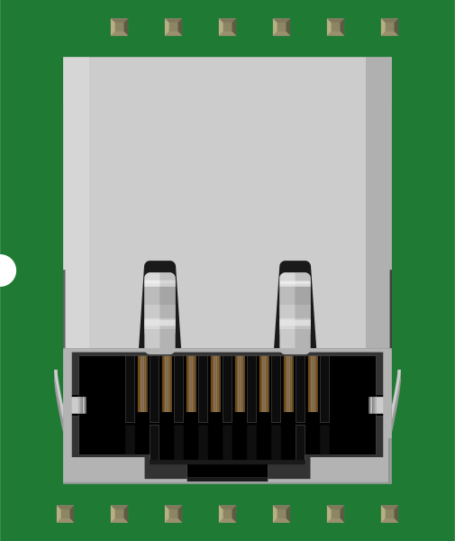
 Design with XPORT in Cirkit Designer
Introduction
The XPort by Lantronix is a compact, versatile communication module designed to simplify the integration of devices with Ethernet networks. It enables seamless data exchange and remote control capabilities, making it an ideal solution for IoT applications, industrial automation, and embedded systems. The XPort module encapsulates all the essential networking features, including a built-in web server, TCP/IP stack, and Ethernet interface, in a small form factor.
Explore Projects Built with XPORT
 Open Project in Cirkit Designer
 Open Project in Cirkit Designer
 Open Project in Cirkit Designer
 Open Project in Cirkit Designer
Explore Projects Built with XPORT
Open Project in Cirkit DesignerOpen Project in Cirkit DesignerOpen Project in Cirkit DesignerOpen Project in Cirkit DesignerCommon Applications and Use Cases
- Industrial Automation: Remote monitoring and control of machinery and equipment.
- IoT Devices: Enabling network connectivity for smart devices.
- Embedded Systems: Adding Ethernet communication to microcontroller-based systems.
- Building Automation: Integration of HVAC, lighting, and security systems.
- Medical Devices: Secure data transmission for patient monitoring systems.
Technical Specifications
The XPort module is designed to provide robust and reliable network connectivity. Below are its key technical specifications:
General Specifications
| Parameter | Value |
|---|---|
| Manufacturer | Lantronix |
| Part Number | XPort |
| Network Interface | 10/100 Mbps Ethernet |
| Protocols Supported | TCP, UDP, HTTP, FTP, Telnet, SNMP, DHCP |
| Operating Voltage | 3.3V DC |
| Power Consumption | 265 mA (typical) |
| Dimensions | 33.9mm x 16.25mm x 13.5mm |
| Operating Temperature | -40°C to +85°C |
Pin Configuration and Descriptions
The XPort module has a 10-pin interface for connecting to a host system. Below is the pinout and description:
| Pin Number | Pin Name | Description |
|---|---|---|
| 1 | GND | Ground |
| 2 | VCC | Power supply input (3.3V DC) |
| 3 | RXD | Receive data (UART input) |
| 4 | TXD | Transmit data (UART output) |
| 5 | RTS | Request to send (UART control) |
| 6 | CTS | Clear to send (UART control) |
| 7 | RESET | Active-low reset input |
| 8 | Status LED | Indicates module status |
| 9 | Ethernet TX+ | Ethernet transmit positive |
| 10 | Ethernet TX- | Ethernet transmit negative |
Usage Instructions
The XPort module is straightforward to use and can be integrated into a variety of systems. Below are the steps and best practices for using the XPort module:
Connecting the XPort to a Circuit
- Power Supply: Connect the VCC pin to a 3.3V DC power source and the GND pin to ground.
- UART Interface: Connect the RXD and TXD pins to the corresponding UART pins of your microcontroller or host device.
- Ethernet Interface: Connect the Ethernet TX+ and TX- pins to an Ethernet RJ45 connector for network communication.
- Reset: Optionally, connect the RESET pin to a push-button or microcontroller GPIO for resetting the module.
Important Considerations
- Ensure the power supply is stable and within the specified voltage range (3.3V DC).
- Use proper decoupling capacitors near the VCC pin to minimize noise.
- Configure the UART baud rate and settings to match the XPort's default or desired configuration.
- Use shielded Ethernet cables for reliable network communication in noisy environments.
Example: Using XPort with Arduino UNO
The XPort module can be connected to an Arduino UNO for basic communication. Below is an example of how to send data over Ethernet using the XPort:
Wiring Diagram
- Connect XPort's RXD to Arduino's TX (Pin 1).
- Connect XPort's TXD to Arduino's RX (Pin 0).
- Connect XPort's VCC to Arduino's 3.3V pin.
- Connect XPort's GND to Arduino's GND.
Arduino Code Example
// Include necessary libraries
#include <SoftwareSerial.h>

// Define RX and TX pins for SoftwareSerial
SoftwareSerial xportSerial(10, 11); // RX = Pin 10, TX = Pin 11

void setup() {
  // Initialize serial communication with XPort
  xportSerial.begin(9600); // Default baud rate for XPort
  Serial.begin(9600);      // For debugging via Serial Monitor

  // Send initialization message
  Serial.println("XPort Communication Initialized");
  xportSerial.println("Hello, XPort!"); // Send data to XPort
}

void loop() {
  // Check if data is available from XPort
  if (xportSerial.available()) {
    String data = xportSerial.readString(); // Read data from XPort
    Serial.print("Received from XPort: ");
    Serial.println(data); // Print received data to Serial Monitor
  }

  // Check if data is available from Serial Monitor
  if (Serial.available()) {
    String data = Serial.readString(); // Read data from Serial Monitor
    xportSerial.println(data);         // Send data to XPort
  }
}
Notes:
- Replace
9600with the appropriate baud rate if the XPort is configured differently. - Avoid using the Arduino's hardware serial pins (0 and 1) for other purposes when using the XPort.
Troubleshooting and FAQs
Common Issues and Solutions
No Communication with XPort
- Ensure the power supply is stable and within the specified range (3.3V DC).
- Verify the UART connections (RXD and TXD) are correctly wired.
- Check the baud rate configuration of the XPort and the host device.
Ethernet Connection Fails
- Confirm the Ethernet cable is properly connected and functional.
- Verify the network settings (IP address, subnet mask, gateway) are correctly configured.
- Use a network analyzer tool to check for packet transmission.
Module Does Not Respond
- Check the RESET pin to ensure the module is not held in a reset state.
- Verify the power supply voltage and current requirements are met.
FAQs
Q: Can the XPort module be used with 5V systems?
A: The XPort operates at 3.3V. Use a level shifter or voltage divider for interfacing with 5V systems.
Q: How do I configure the XPort's network settings?
A: The XPort can be configured via its built-in web server or using the Lantronix DeviceInstaller software.
Q: What is the default baud rate of the XPort?
A: The default baud rate is 9600 bps, but it can be changed via configuration.
Q: Can the XPort be used in outdoor environments?
A: The XPort is rated for an operating temperature range of -40°C to +85°C. Ensure it is housed in a weatherproof enclosure for outdoor use.