How to Use Actuonix L16-P Linear Actuator (left facing): Examples, Pinouts, and Specs
Introduction
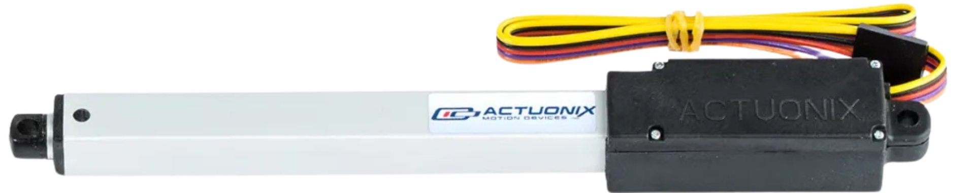
The Actuonix L16-P Linear Actuator (Part ID: L16-100-63-12-P) is a compact and versatile linear actuator designed to provide precise linear motion. This model features a left-facing design, making it ideal for applications where space constraints or specific mechanical configurations are a concern. The L16-P is equipped with a potentiometer for position feedback, enabling precise control in automation and robotics systems.
Explore Projects Built with Actuonix L16-P Linear Actuator (left facing)
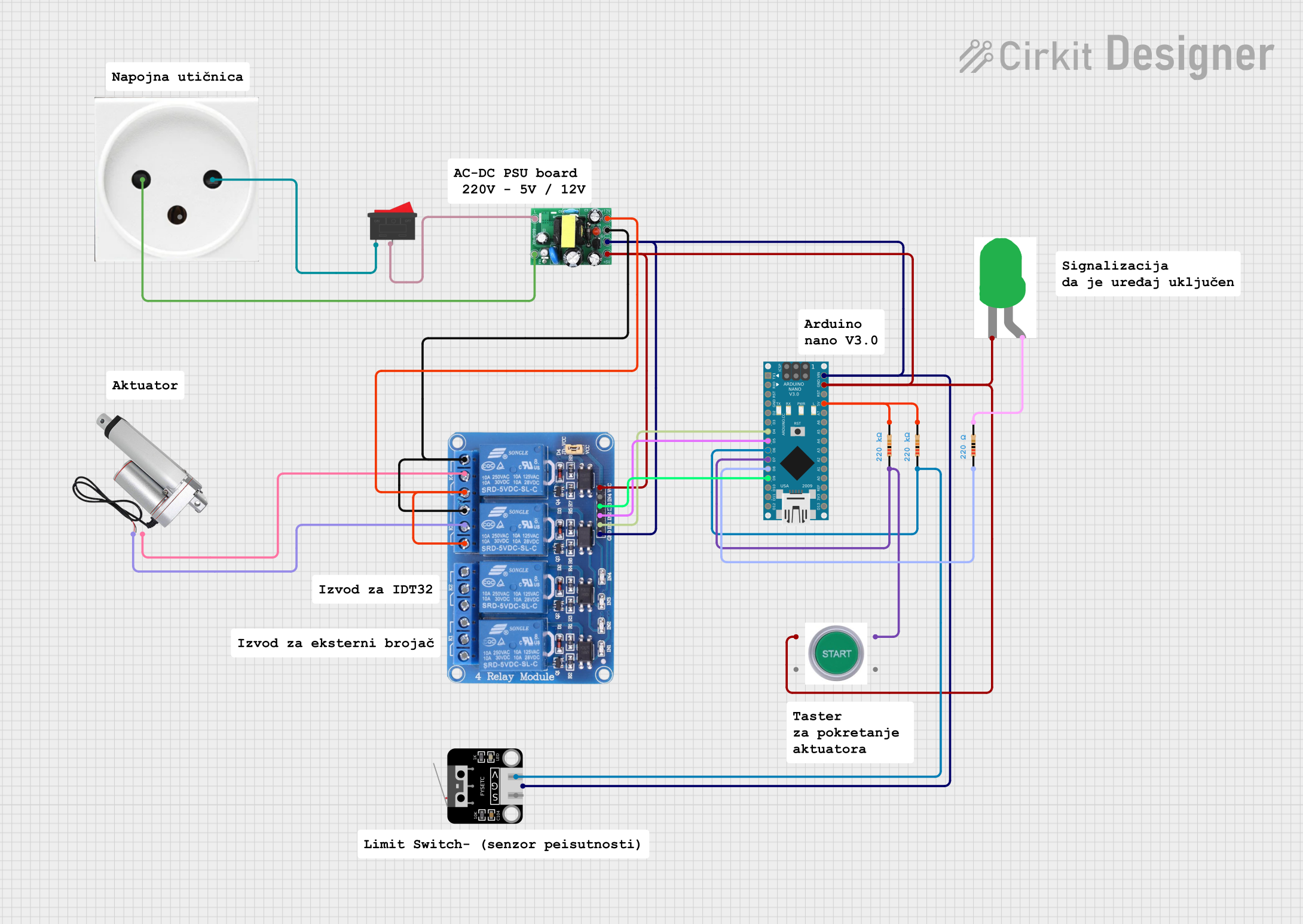

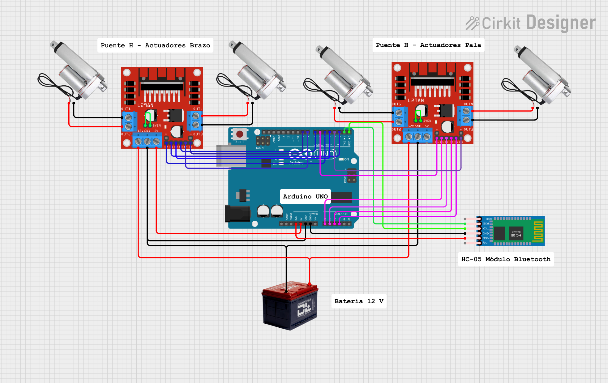
Explore Projects Built with Actuonix L16-P Linear Actuator (left facing)
Common Applications
- Robotics and automation systems
- Industrial machinery requiring linear motion
- Adjustable furniture and ergonomic equipment
- Medical devices and laboratory equipment
- Remote-controlled vehicles and drones
Technical Specifications
Key Specifications
| Parameter | Value |
|---|---|
| Manufacturer | Actuonix |
| Part ID | L16-100-63-12-P |
| Stroke Length | 100 mm |
| Input Voltage | 12 V DC |
| Maximum Force | 63 N |
| Speed (No Load) | 12 mm/s |
| Feedback Type | Potentiometer |
| Body Material | Anodized Aluminum |
| Operating Temperature Range | -10°C to +50°C |
| Duty Cycle | 20% at full load |
| Connector Type | 6-pin JST |
Pin Configuration
The L16-P Linear Actuator features a 6-pin JST connector for power, control, and feedback. The pinout is as follows:
| Pin Number | Wire Color | Function |
|---|---|---|
| 1 | Red | Motor Power (+12 V) |
| 2 | Black | Motor Ground (GND) |
| 3 | Blue | Potentiometer Signal (Output) |
| 4 | Green | Potentiometer Ground (GND) |
| 5 | Yellow | Potentiometer Power (+5 V) |
| 6 | White | Not Connected (NC) |
Usage Instructions
How to Use the L16-P in a Circuit
- Power Supply: Connect the red wire to a 12 V DC power source and the black wire to ground. Ensure the power supply can handle the actuator's current requirements.
- Position Feedback: Use the potentiometer output (blue wire) to monitor the actuator's position. Connect the green wire to ground and the yellow wire to a 5 V reference voltage.
- Control: The actuator can be controlled using an H-bridge motor driver or a microcontroller with PWM (Pulse Width Modulation) capabilities.
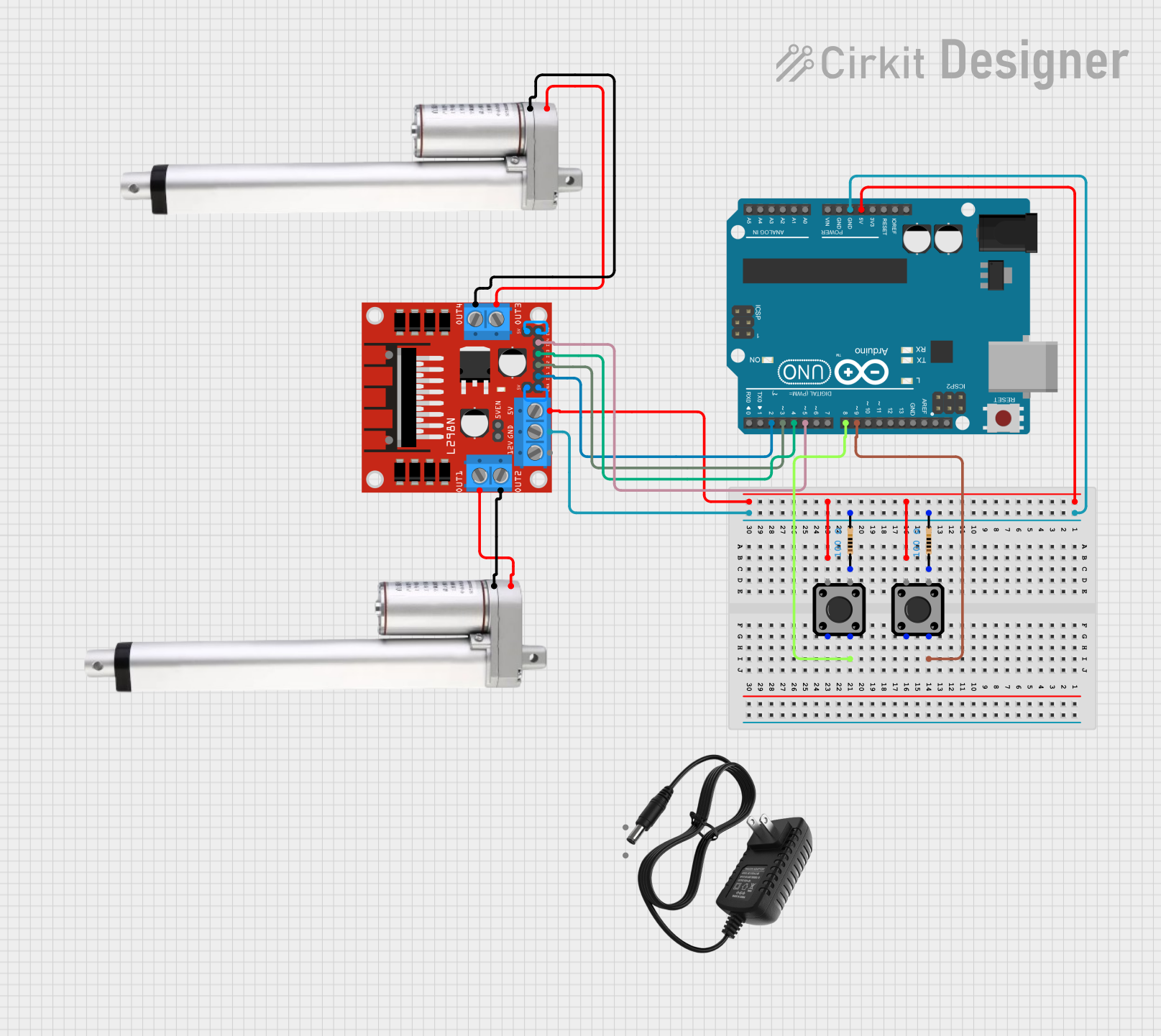
Example: Connecting to an Arduino UNO
Below is an example of how to control the L16-P Linear Actuator using an Arduino UNO. The potentiometer feedback is used to monitor the actuator's position.
Circuit Connections
- Connect the red wire to the motor driver's output (12 V).
- Connect the black wire to the motor driver's ground.
- Connect the blue wire to an analog input pin on the Arduino (e.g., A0).
- Connect the green wire to the Arduino's GND.
- Connect the yellow wire to the Arduino's 5 V pin.
Arduino Code
// Define pins for actuator control and feedback
const int potPin = A0; // Potentiometer feedback connected to A0
const int motorPin1 = 9; // Motor control pin 1 (PWM)
const int motorPin2 = 10; // Motor control pin 2 (PWM)

// Variables to store potentiometer readings
int potValue = 0;
int targetPosition = 512; // Target position (0-1023 for 10-bit ADC)

void setup() {
  pinMode(motorPin1, OUTPUT);
  pinMode(motorPin2, OUTPUT);
  Serial.begin(9600); // Initialize serial communication for debugging
}

void loop() {
  // Read the potentiometer value
  potValue = analogRead(potPin);
  Serial.print("Potentiometer Value: ");
  Serial.println(potValue);

  // Control the actuator to move toward the target position
  if (potValue < targetPosition - 10) {
    // Move actuator forward
    analogWrite(motorPin1, 150); // Adjust PWM value as needed
    analogWrite(motorPin2, 0);
  } else if (potValue > targetPosition + 10) {
    // Move actuator backward
    analogWrite(motorPin1, 0);
    analogWrite(motorPin2, 150); // Adjust PWM value as needed
  } else {
    // Stop the actuator
    analogWrite(motorPin1, 0);
    analogWrite(motorPin2, 0);
  }

  delay(10); // Small delay for stability
}
Important Considerations
- Power Supply: Ensure the power supply provides sufficient current for the actuator's operation.
- Duty Cycle: Operate the actuator within its rated duty cycle (20% at full load) to prevent overheating.
- Position Feedback: Use the potentiometer feedback for precise control in closed-loop systems.
- Mounting: Securely mount the actuator to prevent misalignment or mechanical stress.
Troubleshooting and FAQs
Common Issues and Solutions
Actuator Does Not Move
- Verify the power supply voltage is 12 V DC.
- Check the motor driver connections and ensure proper control signals are being sent.
- Ensure the actuator is not overloaded beyond its maximum force rating (63 N).
Inaccurate Position Feedback
- Verify the potentiometer connections (blue, green, and yellow wires).
- Ensure the potentiometer is powered with a stable 5 V reference voltage.
- Check for noise or interference in the analog signal.
Overheating
- Ensure the actuator is operated within its duty cycle (20% at full load).
- Allow sufficient cooling time between operations.
No Feedback Signal
- Confirm the potentiometer ground (green wire) is connected to the system ground.
- Check the analog input pin on the microcontroller for proper configuration.
FAQs
Q: Can the L16-P be used with a 24 V power supply?
A: No, the L16-P is designed for 12 V DC operation. Using a higher voltage may damage the actuator.
Q: How do I determine the actuator's position?
A: The potentiometer output (blue wire) provides an analog voltage proportional to the actuator's position. Use an ADC (Analog-to-Digital Converter) to read this value.
Q: Can the actuator be used in outdoor environments?
A: The L16-P is not rated for outdoor use. Protect it from moisture, dust, and extreme temperatures to ensure reliable operation.
Q: What is the lifespan of the actuator?
A: The lifespan depends on the operating conditions, load, and duty cycle. Proper usage and maintenance can extend its life significantly.