Cirkit Designer Logo
Cirkit Designer
Your all-in-one circuit design IDE
Home / 
Component Documentation

How to Use ESP 32: Examples, Pinouts, and Specs

Image of ESP 32
Cirkit Designer LogoDesign with ESP 32 in Cirkit Designer

Introduction

The ESP32 is a low-cost, low-power system on a chip (SoC) developed by Espressif Systems. It features integrated Wi-Fi and Bluetooth capabilities, making it an ideal choice for Internet of Things (IoT) applications, smart devices, and embedded systems. With its dual-core processor, extensive GPIO options, and support for various communication protocols, the ESP32 is a versatile and powerful component for a wide range of projects.

Explore Projects Built with ESP 32

Use Cirkit Designer to design, explore, and prototype these projects online. Some projects support real-time simulation. Click "Open Project" to start designing instantly!
ESP32-Based RF Communication System with 433 MHz Modules
Image of 433 mhz: A project utilizing ESP 32 in a practical application
This circuit comprises an ESP32 microcontroller connected to a 433 MHz RF transmitter and receiver pair. The ESP32 is programmed to receive and decode RF signals through the receiver module, as well as send RF signals via the transmitter module. Additionally, the ESP32 can communicate with a Bluetooth device to exchange commands and data, and it uses an LED for status indication.
Cirkit Designer LogoOpen Project in Cirkit Designer
ESP32-Based Environmental Monitoring System with Motion Detection
Image of pro: A project utilizing ESP 32 in a practical application
This circuit features an ESP32 microcontroller on a baseboard that interfaces with a PIR sensor for motion detection, a DHT22 sensor for measuring temperature and humidity, and a BH1750 sensor for detecting ambient light levels. The ESP32 is configured to communicate with the BH1750 using I2C protocol, with GPIO22 and GPIO21 serving as the SCL and SDA lines, respectively. Power is supplied to the sensors from the ESP32's voltage output pins, and sensor outputs are connected to designated GPIO pins for data acquisition.
Cirkit Designer LogoOpen Project in Cirkit Designer
ESP32-Based Smart Ethernet Weather Station with DHT22 Sensor and Relay Control
Image of ESP32 Single and Double AC with Temp 30Pin Micro and USBC: A project utilizing ESP 32 in a practical application
This circuit features an ESP32 microcontroller interfaced with a W5500 Ethernet module, a DHT22 temperature and humidity sensor, and a 2-channel relay module. The ESP32 is configured to communicate with the W5500 module via SPI for network connectivity, read sensor data from the DHT22, and control devices through the relay module. The purpose of this circuit is likely for environmental monitoring and control over a network.
Cirkit Designer LogoOpen Project in Cirkit Designer
ESP32-Based Sensor Monitoring System with OLED Display and E-Stop
Image of MVP_design: A project utilizing ESP 32 in a practical application
This circuit features an ESP32 microcontroller that interfaces with a variety of sensors and output devices. It is powered by a Lipo battery through a buck converter, ensuring a stable voltage supply. The ESP32 collects data from a DHT11 temperature and humidity sensor and a vibration sensor, controls a buzzer, and displays information on an OLED screen. An emergency stop (E Stop) is connected for safety purposes, allowing the system to be quickly deactivated.
Cirkit Designer LogoOpen Project in Cirkit Designer

Explore Projects Built with ESP 32

Use Cirkit Designer to design, explore, and prototype these projects online. Some projects support real-time simulation. Click "Open Project" to start designing instantly!
Image of 433 mhz: A project utilizing ESP 32 in a practical application
ESP32-Based RF Communication System with 433 MHz Modules
This circuit comprises an ESP32 microcontroller connected to a 433 MHz RF transmitter and receiver pair. The ESP32 is programmed to receive and decode RF signals through the receiver module, as well as send RF signals via the transmitter module. Additionally, the ESP32 can communicate with a Bluetooth device to exchange commands and data, and it uses an LED for status indication.
Cirkit Designer LogoOpen Project in Cirkit Designer
Image of pro: A project utilizing ESP 32 in a practical application
ESP32-Based Environmental Monitoring System with Motion Detection
This circuit features an ESP32 microcontroller on a baseboard that interfaces with a PIR sensor for motion detection, a DHT22 sensor for measuring temperature and humidity, and a BH1750 sensor for detecting ambient light levels. The ESP32 is configured to communicate with the BH1750 using I2C protocol, with GPIO22 and GPIO21 serving as the SCL and SDA lines, respectively. Power is supplied to the sensors from the ESP32's voltage output pins, and sensor outputs are connected to designated GPIO pins for data acquisition.
Cirkit Designer LogoOpen Project in Cirkit Designer
Image of ESP32 Single and Double AC with Temp 30Pin Micro and USBC: A project utilizing ESP 32 in a practical application
ESP32-Based Smart Ethernet Weather Station with DHT22 Sensor and Relay Control
This circuit features an ESP32 microcontroller interfaced with a W5500 Ethernet module, a DHT22 temperature and humidity sensor, and a 2-channel relay module. The ESP32 is configured to communicate with the W5500 module via SPI for network connectivity, read sensor data from the DHT22, and control devices through the relay module. The purpose of this circuit is likely for environmental monitoring and control over a network.
Cirkit Designer LogoOpen Project in Cirkit Designer
Image of MVP_design: A project utilizing ESP 32 in a practical application
ESP32-Based Sensor Monitoring System with OLED Display and E-Stop
This circuit features an ESP32 microcontroller that interfaces with a variety of sensors and output devices. It is powered by a Lipo battery through a buck converter, ensuring a stable voltage supply. The ESP32 collects data from a DHT11 temperature and humidity sensor and a vibration sensor, controls a buzzer, and displays information on an OLED screen. An emergency stop (E Stop) is connected for safety purposes, allowing the system to be quickly deactivated.
Cirkit Designer LogoOpen Project in Cirkit Designer

Common Applications and Use Cases

  • IoT devices and smart home automation
  • Wireless sensor networks
  • Wearable electronics
  • Robotics and automation systems
  • Data logging and remote monitoring
  • Bluetooth-enabled devices

Technical Specifications

Key Technical Details

Specification Value
Microcontroller Xtensa® 32-bit LX6 dual-core processor
Clock Speed Up to 240 MHz
Flash Memory 4 MB (varies by model)
SRAM 520 KB
Wi-Fi Standard 802.11 b/g/n
Bluetooth v4.2 BR/EDR and BLE
Operating Voltage 3.3V
GPIO Pins Up to 36
ADC Channels 18 (12-bit resolution)
DAC Channels 2
Communication Interfaces UART, SPI, I2C, I2S, CAN, PWM
Power Consumption Ultra-low power (varies by mode)
Operating Temperature -40°C to +125°C

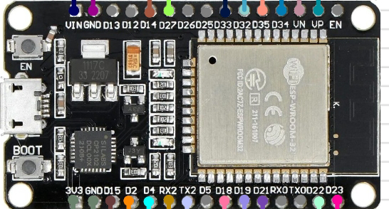
Pin Configuration and Descriptions

The ESP32 has multiple variants, but the following table outlines the general pin configuration for the ESP32-WROOM-32 module:

Pin Number Pin Name Description
1 EN Enable pin (active high)
2 IO0 GPIO0, used for boot mode selection
3 IO1 (TX0) GPIO1, UART0 TX
4 IO3 (RX0) GPIO3, UART0 RX
5 IO4 GPIO4, general-purpose I/O
6 IO5 GPIO5, general-purpose I/O
7 IO12 GPIO12, ADC2 channel 5
8 IO13 GPIO13, ADC2 channel 4
9 IO14 GPIO14, ADC2 channel 6
10 IO15 GPIO15, ADC2 channel 3
... ... ... (varies by specific ESP32 module)

Note: Refer to the datasheet of your specific ESP32 module for a complete pinout.

Usage Instructions

How to Use the ESP32 in a Circuit

  1. Powering the ESP32:

    • The ESP32 operates at 3.3V. Ensure your power supply provides a stable 3.3V.
    • If using a development board (e.g., ESP32 DevKit), you can power it via USB or a 5V input.
  2. Connecting GPIO Pins:

    • Use GPIO pins for interfacing with sensors, actuators, and other peripherals.
    • Be cautious of the 3.3V logic level; use level shifters if interfacing with 5V devices.
  3. Programming the ESP32:

    • The ESP32 can be programmed using the Arduino IDE, Espressif's ESP-IDF, or other platforms.
    • Install the necessary board support package (BSP) in your IDE before programming.
  4. Wi-Fi and Bluetooth Setup:

    • Use the built-in libraries (e.g., WiFi.h for Arduino) to connect to Wi-Fi networks.
    • For Bluetooth, use the BluetoothSerial or BLE libraries.

Example Code: Blink an LED

Below is an example of how to blink an LED connected to GPIO2 using the Arduino IDE:

// Include necessary libraries
void setup() {
  pinMode(2, OUTPUT); // Set GPIO2 as an output pin
}

void loop() {
  digitalWrite(2, HIGH); // Turn the LED on
  delay(1000);           // Wait for 1 second
  digitalWrite(2, LOW);  // Turn the LED off
  delay(1000);           // Wait for 1 second
}

Important Considerations and Best Practices

  • Voltage Levels: Ensure all connected devices operate at 3.3V logic levels to avoid damaging the ESP32.
  • Boot Mode: GPIO0 must be pulled low during boot to enter programming mode.
  • Power Supply: Use a stable power source to avoid unexpected resets or malfunctions.
  • Heat Management: The ESP32 can get warm during operation; ensure proper ventilation.

Troubleshooting and FAQs

Common Issues and Solutions

  1. ESP32 Not Detected by Computer:

    • Ensure the correct USB driver (e.g., CP210x or CH340) is installed.
    • Check the USB cable for data transfer capability (some cables are power-only).
  2. Program Upload Fails:

    • Verify that GPIO0 is pulled low during programming.
    • Check the selected COM port and board type in the IDE.
  3. Wi-Fi Connection Issues:

    • Double-check the SSID and password in your code.
    • Ensure the Wi-Fi network operates on the 2.4 GHz band (ESP32 does not support 5 GHz).
  4. Random Resets or Instability:

    • Use a stable 3.3V power supply with sufficient current (at least 500 mA).
    • Add decoupling capacitors near the power pins.

FAQs

Q: Can the ESP32 operate on battery power?
A: Yes, the ESP32 supports low-power modes, making it suitable for battery-powered applications. Use a LiPo battery with a 3.3V regulator for optimal performance.

Q: How do I use the ESP32's Bluetooth functionality?
A: Use the BluetoothSerial library for classic Bluetooth or the BLE library for Bluetooth Low Energy (BLE). Examples are available in the Arduino IDE.

Q: Can I use the ESP32 with 5V sensors?
A: Yes, but you must use a level shifter to convert the 5V signals to 3.3V to avoid damaging the ESP32.

Q: What is the maximum range of the ESP32's Wi-Fi?
A: The range depends on environmental factors but typically extends up to 100 meters in open spaces.

By following this documentation, you can effectively integrate the ESP32 into your projects and troubleshoot common issues.