How to Use STM32F4 BlackPill: Examples, Pinouts, and Specs
Introduction
The STM32F4 BlackPill is a compact and versatile microcontroller development board designed by WeAct Studio. Based on the high-performance STM32F4 series from STMicroelectronics, this board is an excellent choice for embedded applications requiring a balance between processing power, low power consumption, and a rich set of peripherals. Common applications include robotics, custom controllers, hobbyist projects, and educational purposes.
Explore Projects Built with STM32F4 BlackPill
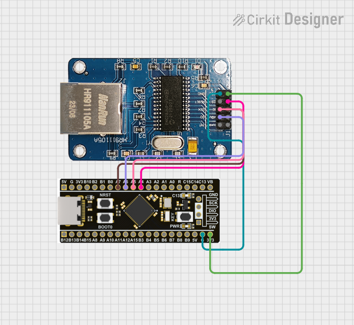


Explore Projects Built with STM32F4 BlackPill
Technical Specifications
Key Technical Details
- Microcontroller: STM32F405RG
- Core: ARM Cortex-M4 with FPU and DSP instructions
- Operating Voltage: 3.3V
- Input Voltage: 5V via USB-C or VIN pin
- Clock Speed: Up to 168 MHz
- Flash Memory: 1 MB
- SRAM: 192+4 KB
- I/O Pins: 37
- Analog Input Pins: 12 (ADC with 12-bit resolution)
- Interfaces: I2C, SPI, UART, CAN, USB
- PWM Channels: 12
- Communication: USB 2.0 Full-Speed, 3x I2C, 3x SPI, 4x USART, 2x CAN
- Debugging: SWD (Serial Wire Debug)
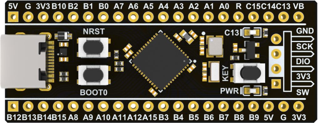
Pin Configuration and Descriptions
| Pin Number | Function | Description |
|---|---|---|
| 1 | VBAT | Battery input for RTC |
| 2 | PC13 | User button |
| 3-16 | PA0 - PA15 | GPIO, ADC, various functions |
| 17-30 | PB0 - PB15 | GPIO, ADC, various functions |
| 31-37 | PC0 - PC6 | GPIO, ADC, various functions |
| 38 | 3.3V | 3.3V power supply output |
| 39 | 5V | 5V power supply input/output |
| 40 | GND | Ground |
| 41 | BOOT0 | Boot configuration pin |
| 42 | VBUS | USB VBUS sensing |
| 43 | PA13 (SWDIO) | Serial Wire Debug I/O |
| 44 | PA14 (SWCLK) | Serial Wire Debug Clock |
| 45 | RESET | Reset input |
Usage Instructions
Integrating with a Circuit
To use the STM32F4 BlackPill in a circuit:
- Powering the Board: Connect 5V to the '5V' pin or USB-C for power. Alternatively, supply 3.3V directly to the '3.3V' pin.
- Programming: Connect the SWDIO and SWCLK pins to an ST-Link or similar programmer/debugger for programming.
- GPIO: Utilize the I/O pins as required by your application, ensuring you do not exceed the maximum current ratings.
Best Practices
- ESD Precautions: Always handle the board with proper electrostatic discharge precautions.
- Decoupling Capacitors: Place decoupling capacitors close to the power pins if the board is part of a larger system.
- Firmware Development: Use STM32CubeIDE or similar development environments for firmware development.
- Boot Configuration: Ensure BOOT0 is set to the correct position for normal operation or bootloader mode as needed.
Troubleshooting and FAQs
Common Issues
- Board Not Recognized: Ensure drivers are installed and the USB cable is functioning.
- Programming Failure: Check connections to the SWD pins and verify the correct programming settings.
- Unexpected Behavior: Double-check the power supply and ensure the board is not being over-driven.
Solutions and Tips
- Driver Installation: Make sure to install the STM32 virtual COM port drivers for USB connectivity.
- Power Supply: Use a stable power source capable of delivering sufficient current.
- Firmware Updates: Keep the board's firmware up to date with the latest releases from STMicroelectronics.
FAQs
Q: Can I power the board using the VIN pin?
A: Yes, you can supply 5V to the VIN pin to power the board.
Q: What is the maximum operating temperature?
A: The STM32F405RG operates within a temperature range of -40°C to 85°C.
Q: How do I reset the board?
A: You can reset the board by momentarily connecting the RESET pin to GND.
Example Code for Arduino UNO
Below is an example of how to blink an LED connected to PA5 on the STM32F4 BlackPill using the Arduino IDE:
// Define the LED pin
const int ledPin = PA5;

// the setup routine runs once when you press reset:
void setup() {
  // initialize the digital pin as an output.
  pinMode(ledPin, OUTPUT);
}

// the loop routine runs over and over again forever:
void loop() {
  digitalWrite(ledPin, HIGH);   // turn the LED on (HIGH is the voltage level)
  delay(1000);                  // wait for a second
  digitalWrite(ledPin, LOW);    // turn the LED off by making the voltage LOW
  delay(1000);                  // wait for a second
}
Remember to select the correct board and processor from the Arduino IDE's Tools menu before uploading the code.