How to Use Sparkfun Rotary Encoder: Examples, Pinouts, and Specs
Introduction
The SparkFun Rotary Encoder is a device that converts the angular position or motion of a shaft or axle into an analog or digital signal. It is commonly used in electronic projects for user input, such as volume control, menu navigation, or precise position adjustments. Unlike a potentiometer, the rotary encoder can rotate infinitely in either direction, making it ideal for applications requiring continuous rotation.
Explore Projects Built with Sparkfun Rotary Encoder
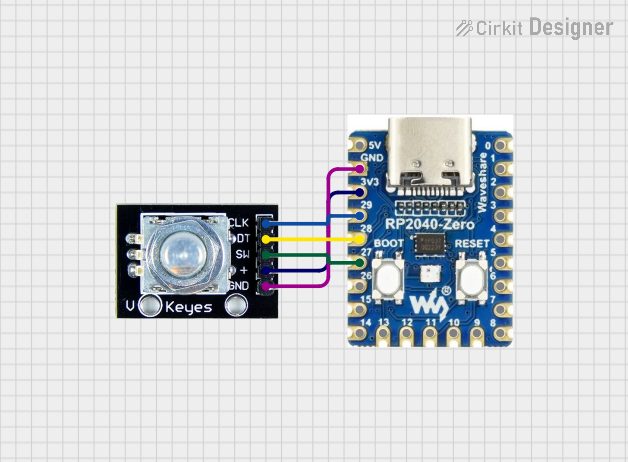
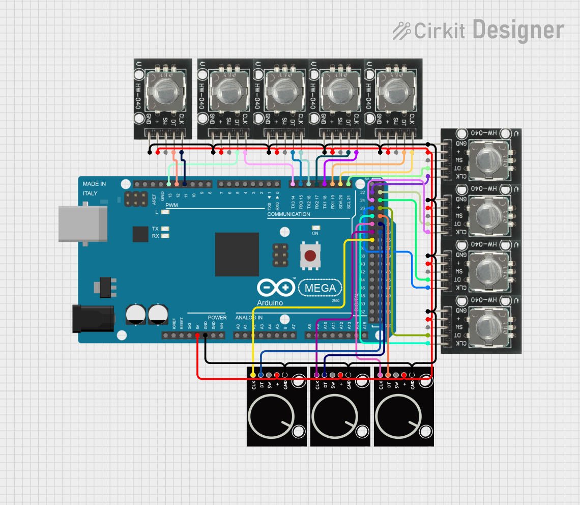
Explore Projects Built with Sparkfun Rotary Encoder
Common Applications
- Volume and brightness control in audio and visual devices
- Menu navigation in embedded systems
- Motor position and speed feedback
- Robotics and automation systems
- Incremental position tracking in CNC machines
Technical Specifications
The SparkFun Rotary Encoder is a mechanical incremental encoder with a push-button switch. Below are its key specifications:
| Parameter | Value |
|---|---|
| Operating Voltage | 3.3V to 5V |
| Output Type | Digital (Quadrature Output) |
| Number of Pulses | 20 pulses per revolution |
| Push-Button Switch | Integrated (momentary type) |
| Shaft Rotation | Continuous (360°) |
| Shaft Diameter | 6mm |
| Mounting Hole Spacing | 15mm |
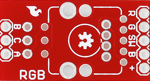
Pin Configuration
The SparkFun Rotary Encoder has five pins. The table below describes each pin:
| Pin Name | Description |
|---|---|
| GND | Ground connection for the encoder. |
| VCC | Power supply pin (3.3V or 5V). |
| SW | Push-button switch output (active LOW). |
| DT | Data pin for quadrature signal (used to determine rotation direction). |
| CLK | Clock pin for quadrature signal (used to determine rotation and pulse count). |
Usage Instructions
Connecting the Rotary Encoder
To use the SparkFun Rotary Encoder in a circuit, follow these steps:
- Connect the VCC pin to a 3.3V or 5V power source.
- Connect the GND pin to the ground of your circuit.
- Connect the CLK and DT pins to two digital input pins on your microcontroller.
- Optionally, connect the SW pin to another digital input pin to use the push-button functionality.
Important Considerations
- Debouncing: The mechanical nature of the encoder may cause signal noise or "bouncing." Use software debouncing or external capacitors to filter out noise.
- Pull-Up Resistors: Ensure that the SW, CLK, and DT pins are connected to pull-up resistors if your microcontroller does not have internal pull-ups enabled.
- Direction Detection: The sequence of signals on the CLK and DT pins determines the direction of rotation. Ensure your code accounts for this.
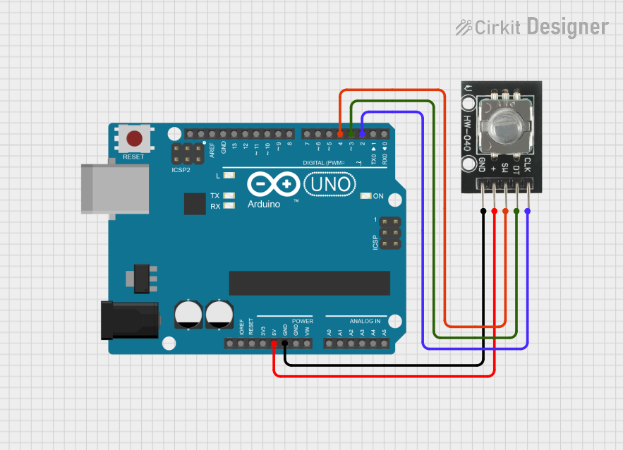
Example Code for Arduino UNO
Below is an example of how to use the SparkFun Rotary Encoder with an Arduino UNO:
// Rotary Encoder Pins
#define CLK 2  // Connect to the CLK pin of the encoder
#define DT 3   // Connect to the DT pin of the encoder
#define SW 4   // Connect to the SW pin of the encoder

int counter = 0;          // Variable to store the encoder position
int currentStateCLK;      // Current state of the CLK pin
int lastStateCLK;         // Previous state of the CLK pin
bool buttonPressed = false; // State of the push-button

void setup() {
  pinMode(CLK, INPUT);    // Set CLK pin as input
  pinMode(DT, INPUT);     // Set DT pin as input
  pinMode(SW, INPUT_PULLUP); // Set SW pin as input with pull-up resistor

  // Read the initial state of the CLK pin
  lastStateCLK = digitalRead(CLK);

  Serial.begin(9600);     // Initialize serial communication
}

void loop() {
  // Read the current state of the CLK pin
  currentStateCLK = digitalRead(CLK);

  // Check if the state of CLK has changed
  if (currentStateCLK != lastStateCLK) {
    // Read the state of the DT pin
    int dtState = digitalRead(DT);

    // Determine the direction of rotation
    if (dtState != currentStateCLK) {
      counter++; // Clockwise rotation
    } else {
      counter--; // Counterclockwise rotation
    }

    // Print the current counter value
    Serial.print("Position: ");
    Serial.println(counter);
  }

  // Update the last state of the CLK pin
  lastStateCLK = currentStateCLK;

  // Check if the push-button is pressed
  if (digitalRead(SW) == LOW) {
    if (!buttonPressed) {
      Serial.println("Button Pressed!");
      buttonPressed = true;
    }
  } else {
    buttonPressed = false;
  }
}
Notes on the Code
- The CLK and DT pins are used to detect rotation and direction. The code compares their states to determine whether the encoder is turned clockwise or counterclockwise.
- The SW pin is used to detect when the push-button is pressed. It is configured with an internal pull-up resistor to ensure stable readings.
Troubleshooting and FAQs
Common Issues
Encoder Not Responding
- Ensure the VCC and GND pins are properly connected.
- Verify that the CLK and DT pins are connected to the correct digital input pins on your microcontroller.
Incorrect Direction Detection
- Check the wiring of the CLK and DT pins. Reversing these connections can cause incorrect direction readings.
- Ensure the code logic for direction detection matches the encoder's signal sequence.
Signal Noise or Erratic Behavior
- Add software debouncing in your code to filter out noise.
- Use a 0.1µF capacitor between the CLK and GND pins, and another between the DT and GND pins, to reduce noise.
Push-Button Not Working
- Verify that the SW pin is connected to a digital input pin with a pull-up resistor.
- Check for mechanical issues with the push-button.
FAQs
Q: Can the rotary encoder be used with 3.3V systems?
A: Yes, the SparkFun Rotary Encoder is compatible with both 3.3V and 5V systems.
Q: How many pulses does the encoder generate per revolution?
A: The encoder generates 20 pulses per revolution.
Q: Can the encoder detect absolute position?
A: No, this is an incremental encoder and does not provide absolute position. It only tracks relative movement.
Q: Is the push-button momentary or latching?
A: The push-button is momentary, meaning it only stays active while pressed.
By following this documentation, you can effectively integrate the SparkFun Rotary Encoder into your projects for precise and reliable user input.