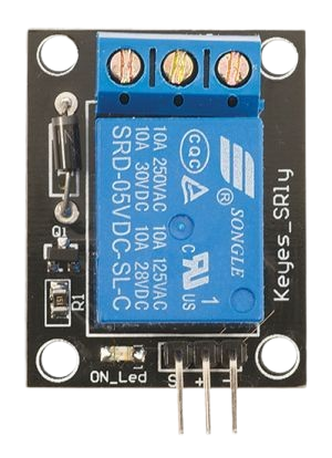
The RELAY SRD-05VDC-SL-C is a compact electromagnetic relay designed to operate at 5V DC. It is widely used in electronic circuits for switching applications, enabling the control of high voltage or high current devices using a low voltage signal. This relay features a Single Pole Double Throw (SPDT) configuration, making it versatile for various applications.
Explore Projects Built with RELAY SRD-05VDC-SL-C
Use Cirkit Designer to design, explore, and prototype these projects online. Some projects support real-time simulation. Click "Open Project" to start designing instantly!
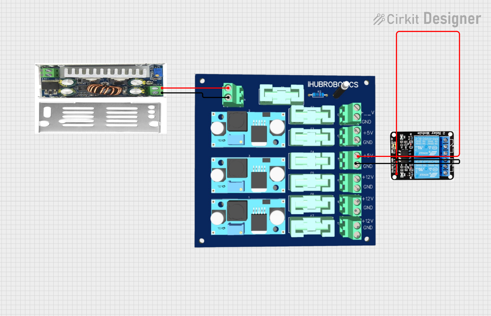
This circuit consists of a DC-DC converter powering a 6-channel power module, which in turn supplies 5V to a 2-relay module. The power module distributes the converted voltage to the relay module, enabling it to control external devices.
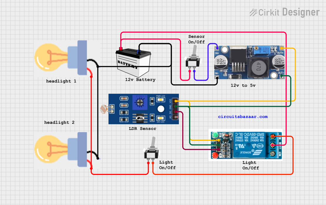
This circuit appears to be a light-activated switch controlling two bulbs using a 5V relay, with an LDR (Light Dependent Resistor) as the sensor. The relay is powered by a 48V to 5V converter, which is switched on by a 12V battery through an SPST toggle switch. The LDR's output is connected to the relay's input, enabling the relay to switch the bulbs on or off based on the ambient light level detected by the LDR.
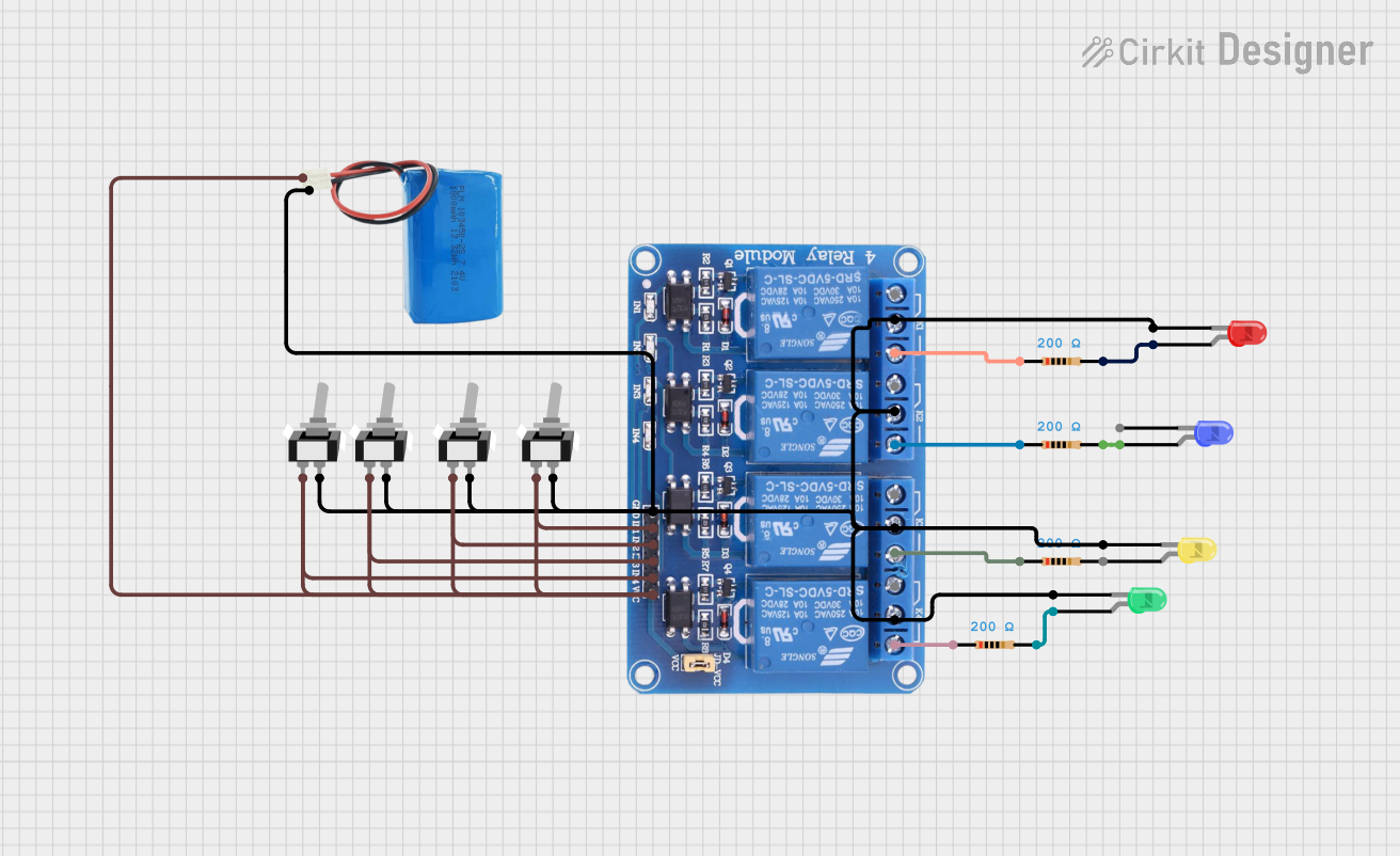
This circuit consists of a 5V battery powering a 4-channel relay module, which controls four LEDs (red, yellow, green, and blue) through individual resistors. Each relay channel is activated by a corresponding SPST toggle switch, allowing manual control of the LEDs.
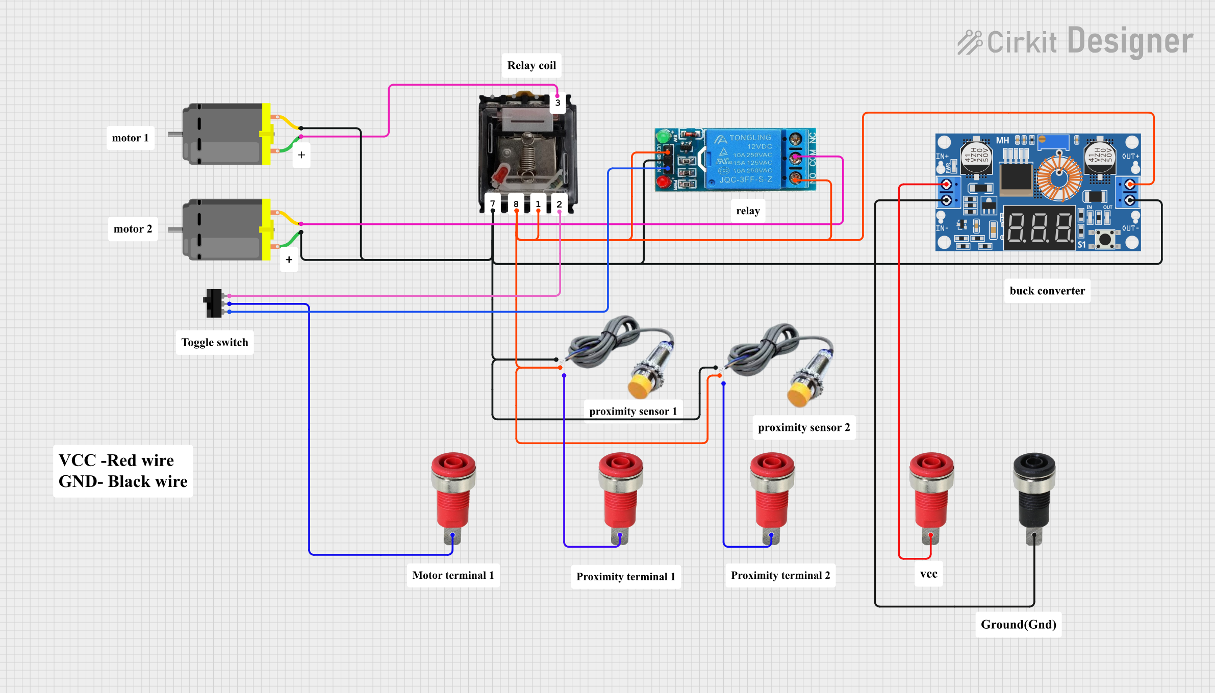
This circuit controls two DC motors using a combination of relays, a toggle switch, and capacitive sensors. The XL4015 DC Buck Step-down module provides regulated power, while the capacitive sensors and toggle switch are used to control the relays, which in turn manage the operation of the motors.
Home automation systems (e.g., controlling lights, fans, or appliances)
Industrial control systems
Motor control circuits
IoT projects
Arduino and microcontroller-based projects
Technical Specifications
Below are the key technical details of the RELAY SRD-05VDC-SL-C:
Parameter
Value
Operating Voltage
5V DC
Coil Resistance
70 Ω ±10%
Switching Voltage
Up to 250V AC / 30V DC
Switching Current
Up to 10A
Contact Configuration
SPDT (Single Pole Double Throw)
Max Power Rating
1250VA (AC) / 300W (DC)
Trigger Current
~71mA
Dimensions
19mm x 15.5mm x 15mm
Weight
~10g
Pin Configuration and Descriptions
The RELAY SRD-05VDC-SL-C has 5 pins, as described in the table below:
Pin Name
Description
Coil+
Positive terminal of the relay coil (connect to 5V DC)
Coil-
Negative terminal of the relay coil (connect to ground)
Common (COM)
Common terminal for the relay's switching contacts
Normally Open (NO)
Open circuit when the relay is inactive; closed when the relay is activated
Normally Closed (NC)
Closed circuit when the relay is inactive; open when the relay is activated
Usage Instructions
How to Use the Component in a Circuit
Power the Relay Coil: Connect the Coil+ pin to a 5V DC power source and the Coil- pin to ground. This energizes the relay coil when activated.
Connect the Load:
For devices that should turn ON when the relay is activated, connect the load between the COM and NO pins.
For devices that should turn OFF when the relay is activated, connect the load between the COM and NC pins.
Control the Relay: Use a microcontroller (e.g., Arduino) or a transistor circuit to control the relay coil. Ensure the control signal provides sufficient current (~71mA) to activate the relay.
Important Considerations and Best Practices
Flyback Diode: Always connect a flyback diode (e.g., 1N4007) across the relay coil to protect the driving circuit from voltage spikes caused by the collapsing magnetic field when the relay is deactivated.
Isolation: Use an optocoupler or transistor to isolate the relay from sensitive microcontroller circuits.
Power Ratings: Ensure the load connected to the relay does not exceed its maximum voltage or current ratings.
Debouncing: If the relay is used in a switching application, consider implementing software or hardware debouncing to avoid erratic behavior.
Example: Connecting to an Arduino UNO
Below is an example of how to control the RELAY SRD-05VDC-SL-C using an Arduino UNO:
Circuit Connections
Connect the Coil+ pin to a digital output pin on the Arduino (e.g., pin 7) through a transistor.
Connect the Coil- pin to ground.
Connect a flyback diode across the relay coil (anode to Coil-, cathode to Coil+).
Connect the load to the COM and NO pins of the relay.
Arduino Code
// Define the relay control pin
const int relayPin = 7;

void setup() {
  pinMode(relayPin, OUTPUT); // Set the relay pin as an output
  digitalWrite(relayPin, LOW); // Ensure the relay is off at startup
}

void loop() {
  digitalWrite(relayPin, HIGH); // Activate the relay
  delay(1000); // Keep the relay on for 1 second
  digitalWrite(relayPin, LOW); // Deactivate the relay
  delay(1000); // Keep the relay off for 1 second
}
Troubleshooting and FAQs
Common Issues and Solutions
Relay Not Activating
Cause: Insufficient current to the relay coil.
Solution: Ensure the control circuit can supply at least 71mA to the relay coil. Use a transistor or relay driver module if necessary.
Load Not Switching
Cause: Incorrect wiring of the load to the relay contacts.
Solution: Verify the load is connected to the correct pins (COM, NO, or NC) based on the desired behavior.
Microcontroller Resetting
Cause: Voltage spikes from the relay coil affecting the microcontroller.
Solution: Add a flyback diode across the relay coil and ensure proper decoupling capacitors are used in the circuit.
Relay Clicking Noise
Cause: Rapid switching or unstable control signal.
Solution: Implement software or hardware debouncing to stabilize the control signal.
FAQs
Q: Can I use the RELAY SRD-05VDC-SL-C with a 3.3V microcontroller?
A: Yes, but you will need a transistor or relay driver circuit to step up the control signal to 5V and provide sufficient current to the relay coil.
Q: What is the purpose of the flyback diode?
A: The flyback diode protects the control circuit from voltage spikes generated when the relay coil is de-energized.
Q: Can this relay handle AC loads?
A: Yes, the relay can switch AC loads up to 250V with a maximum current of 10A. Ensure the load does not exceed these ratings.

 Open Project in Cirkit Designer