How to Use SOLIS: Examples, Pinouts, and Specs
Introduction
Overview: SOLIS is a renowned brand specializing in solar inverters. These devices are essential for converting the direct current (DC) generated by solar panels into alternating current (AC), which is suitable for powering homes, businesses, and other electrical systems. SOLIS inverters are known for their high efficiency, reliability, and user-friendly design. They often include advanced monitoring features to track energy production and system performance.
Common Applications:
- Residential solar energy systems
- Commercial and industrial solar installations
- Off-grid and hybrid solar setups
- Renewable energy monitoring and optimization
Explore Projects Built with SOLIS

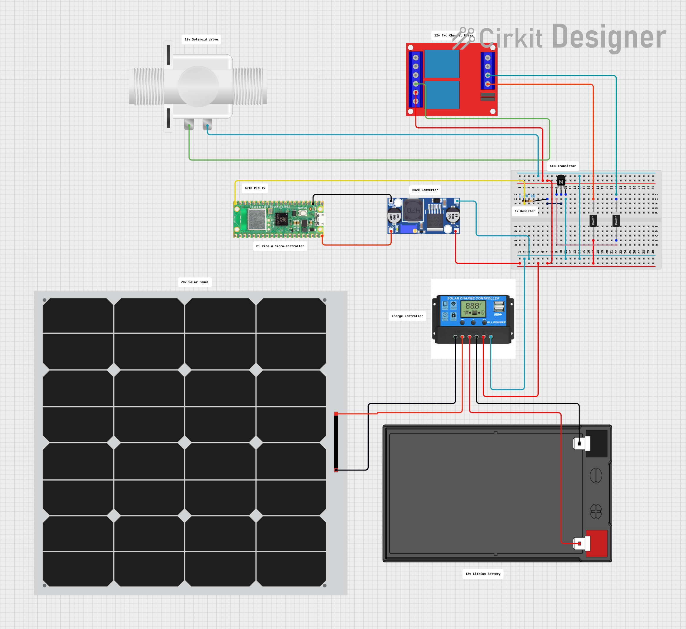

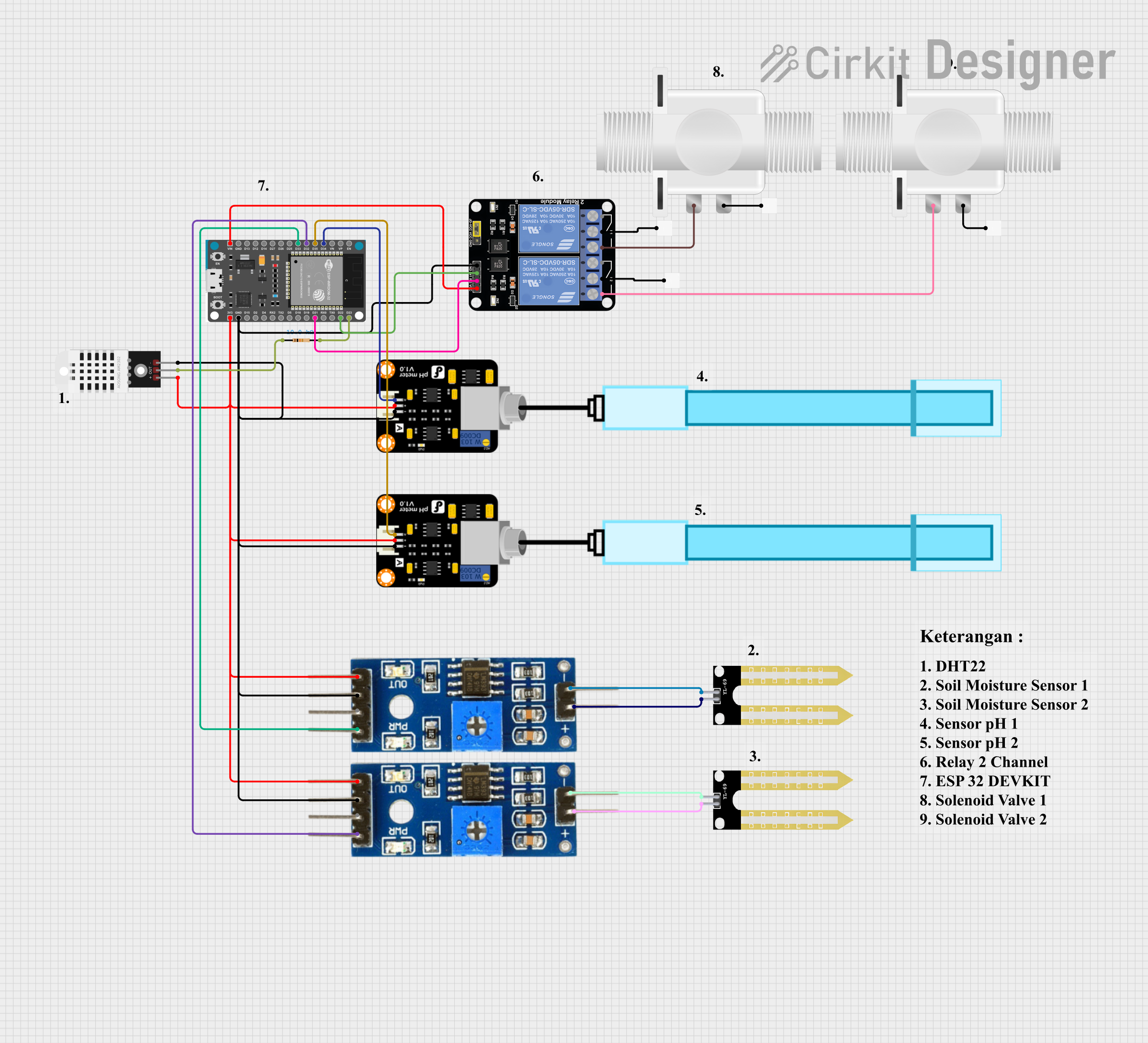
Explore Projects Built with SOLIS
Technical Specifications
Below are the general technical specifications for a typical SOLIS solar inverter. Specifications may vary depending on the specific model.
Key Technical Details
| Parameter | Value |
|---|---|
| Input Voltage Range | 100 VDC – 600 VDC |
| Maximum Input Current | 10 A – 30 A (varies by model) |
| Output Voltage Range | 220 VAC – 240 VAC |
| Output Frequency | 50 Hz / 60 Hz |
| Maximum Efficiency | Up to 98.8% |
| Communication Interfaces | RS485, Wi-Fi, Ethernet, or GPRS (depending on model) |
| Operating Temperature | -25°C to +60°C |
| Protection Features | Overvoltage, undervoltage, overcurrent, short circuit, and surge protection |
| Monitoring Options | Built-in LCD display, mobile app, or web-based monitoring |
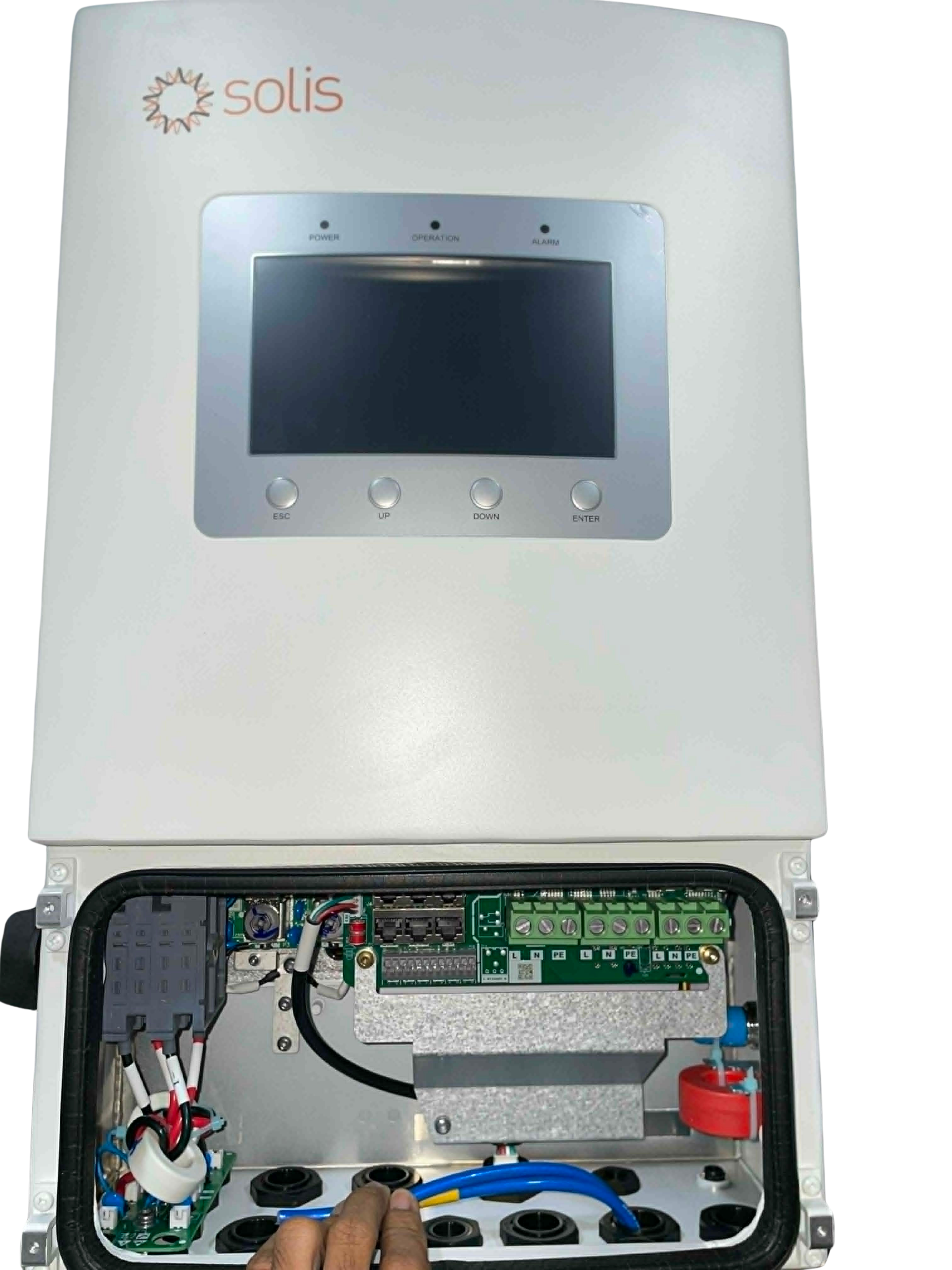
Pin Configuration and Descriptions
The SOLIS inverter typically includes the following input/output connections:
| Pin/Port | Description |
|---|---|
| DC Input (+) | Positive terminal for connecting the solar panel array |
| DC Input (-) | Negative terminal for connecting the solar panel array |
| AC Output (L) | Live wire for AC output to the electrical grid or load |
| AC Output (N) | Neutral wire for AC output to the electrical grid or load |
| Ground (PE) | Protective earth connection for safety |
| Communication Port | Interface for RS485, Wi-Fi, Ethernet, or GPRS communication |
| LCD Display/Buttons | User interface for configuration and monitoring |
Usage Instructions
How to Use the SOLIS Inverter in a Solar System
Installation:
- Mount the inverter securely on a wall or other stable surface, ensuring proper ventilation.
- Connect the DC input terminals to the solar panel array. Ensure correct polarity (positive to positive, negative to negative).
- Connect the AC output terminals to the electrical grid or load. Follow local electrical codes and regulations.
- Connect the ground terminal to the system's grounding point for safety.
Configuration:
- Power on the inverter and use the built-in LCD display or mobile app to configure system settings.
- Set the output voltage and frequency to match the local grid requirements (e.g., 220V, 50Hz).
- If using a communication interface (e.g., Wi-Fi or Ethernet), configure the network settings for remote monitoring.
Monitoring:
- Use the SOLIS mobile app or web portal to monitor energy production, system performance, and fault alerts.
- Regularly check the inverter's LCD display for real-time data and system status.
Important Considerations and Best Practices
- Ensure the inverter is installed in a location protected from direct sunlight, rain, and extreme temperatures.
- Use appropriately rated cables for DC and AC connections to prevent overheating or voltage drops.
- Regularly inspect the system for loose connections, dirt, or debris that may affect performance.
- Follow all safety guidelines and local regulations during installation and operation.
Example Code for Monitoring with Arduino UNO
If you are using the RS485 communication interface to monitor the SOLIS inverter with an Arduino UNO, you can use the following example code:
#include <ModbusMaster.h>

// Create an instance of the ModbusMaster library
ModbusMaster node;

// Define the RS485 communication pins
#define RE_PIN 2  // Receiver Enable pin
#define DE_PIN 3  // Driver Enable pin

void preTransmission() {
  digitalWrite(RE_PIN, HIGH); // Enable RS485 transmitter
  digitalWrite(DE_PIN, HIGH);
}

void postTransmission() {
  digitalWrite(RE_PIN, LOW);  // Disable RS485 transmitter
  digitalWrite(DE_PIN, LOW);
}

void setup() {
  // Initialize serial communication
  Serial.begin(9600);
  Serial.println("SOLIS Inverter Monitoring");

  // Initialize RS485 communication
  pinMode(RE_PIN, OUTPUT);
  pinMode(DE_PIN, OUTPUT);
  digitalWrite(RE_PIN, LOW);
  digitalWrite(DE_PIN, LOW);

  // Configure Modbus communication
  node.begin(1, Serial); // Set Modbus ID to 1
  node.preTransmission(preTransmission);
  node.postTransmission(postTransmission);
}

void loop() {
  uint8_t result;
  uint16_t data;

  // Read inverter data (e.g., voltage at register 0x3100)
  result = node.readInputRegisters(0x3100, 1);
  if (result == node.ku8MBSuccess) {
    data = node.getResponseBuffer(0);
    Serial.print("Voltage: ");
    Serial.print(data / 10.0); // Convert to volts
    Serial.println(" V");
  } else {
    Serial.println("Failed to read data from inverter");
  }

  delay(1000); // Wait 1 second before the next read
}
Troubleshooting and FAQs
Common Issues and Solutions
Inverter Does Not Power On:
- Cause: No DC input from solar panels or incorrect wiring.
- Solution: Check the solar panel connections and ensure sufficient sunlight is available.
Low Energy Output:
- Cause: Shading on solar panels, dirty panels, or system inefficiencies.
- Solution: Clean the solar panels and ensure they are not shaded during peak sunlight hours.
Communication Interface Not Working:
- Cause: Incorrect network settings or faulty communication module.
- Solution: Verify the network configuration and check the communication module for damage.
Overvoltage or Undervoltage Error:
- Cause: Input voltage from solar panels is outside the inverter's operating range.
- Solution: Verify the solar panel array's voltage and adjust the configuration if necessary.
FAQs
Q: Can the SOLIS inverter operate without a grid connection?
- A: Some SOLIS models support off-grid or hybrid operation with battery storage. Check the model specifications.
Q: How do I update the inverter's firmware?
- A: Firmware updates can typically be performed via the SOLIS mobile app or web portal. Follow the instructions provided by the manufacturer.
Q: What maintenance is required for the inverter?
- A: Regularly inspect the inverter for dust, debris, or loose connections. Clean the exterior with a dry cloth and ensure proper ventilation.
Q: Can I expand my solar system with additional inverters?
- A: Yes, SOLIS inverters support parallel operation for system expansion. Consult the user manual for configuration details.