How to Use Power Transformer (dual primary / dual secondary): Examples, Pinouts, and Specs
Introduction
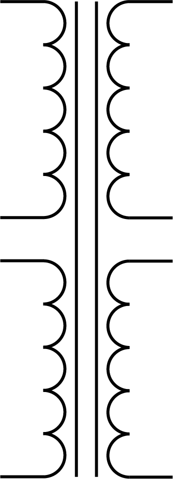
A power transformer with dual primary and dual secondary windings is a versatile electronic component commonly used in power supply circuits. It is designed to step up (increase) or step down (decrease) voltage levels, depending on the application. This type of transformer is particularly useful in situations where different voltage levels are required, or where the power supply needs to be adaptable to various input voltages.
Explore Projects Built with Power Transformer (dual primary / dual secondary)
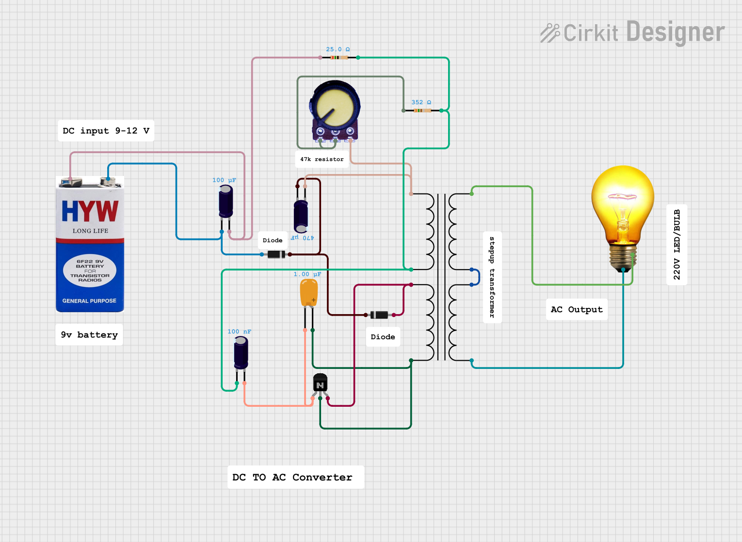


Explore Projects Built with Power Transformer (dual primary / dual secondary)
Common Applications and Use Cases
- Voltage step-up or step-down in power supplies
- Isolation transformer for safety
- Voltage conversion for international equipment compatibility
- Audio amplifiers and other audio equipment
- Industrial control systems
Technical Specifications
Key Technical Details
- Voltage Ratings: Varies depending on the model (e.g., 110V/220V for primary, 12V/24V for secondary)
- Current Ratings: Depends on the transformer's VA (Volt-Ampere) rating
- Power Ratings: Typically expressed in VA or Watts
- Frequency Range: Designed for 50Hz, 60Hz, or sometimes a range covering both
- Isolation Voltage: Specified maximum voltage that can be withstood between windings
- Temperature Range: Operating and storage temperature limits
Pin Configuration and Descriptions
| Pin Number | Description | Primary/Secondary | Note |
|---|---|---|---|
| P1 | Primary Winding 1 Start | Primary | Connect to input voltage |
| P2 | Primary Winding 1 End | Primary | Can be series or parallel |
| P3 | Primary Winding 2 Start | Primary | Connect to input voltage |
| P4 | Primary Winding 2 End | Primary | Can be series or parallel |
| S1 | Secondary Winding 1 Start | Secondary | Output voltage |
| S2 | Secondary Winding 1 End | Secondary | Can be series or parallel |
| S3 | Secondary Winding 2 Start | Secondary | Output voltage |
| S4 | Secondary Winding 2 End | Secondary | Can be series or parallel |
Usage Instructions
How to Use the Component in a Circuit
- Determine Voltage Requirements: Identify the input and output voltage requirements for your circuit.
- Configure Primary Windings: For a higher input voltage, connect the primary windings in series. For a lower input voltage, connect them in parallel.
- Configure Secondary Windings: Similarly, connect the secondary windings in series or parallel to achieve the desired output voltage.
- Connect to Circuit: Integrate the transformer into your circuit, ensuring proper insulation and safety measures are in place.
Important Considerations and Best Practices
- Safety: Always ensure the transformer is de-energized before making connections.
- Heat Dissipation: Provide adequate ventilation around the transformer to prevent overheating.
- Load Matching: Ensure the transformer's power rating matches or exceeds the power requirements of the circuit.
- Isolation: Use an isolation transformer configuration for sensitive electronics to prevent ground loops and reduce noise.
Troubleshooting and FAQs
Common Issues Users Might Face
- Insufficient Voltage Output: Check if the secondary windings are connected properly. Ensure the load does not exceed the transformer's rating.
- Overheating: Ensure proper ventilation and check for overloading or short circuits.
- Humming Noise: This can be due to mechanical resonance or a loose core. Ensure the transformer is securely mounted.
Solutions and Tips for Troubleshooting
- Check Connections: Verify all connections are secure and correct.
- Measure Voltages: Use a multimeter to measure the input and output voltages to ensure they match the expected values.
- Inspect for Damage: Look for signs of physical damage or overheating on the transformer.
FAQs
Q: Can I use this transformer for both stepping up and stepping down voltage? A: Yes, depending on how you connect the primary and secondary windings.
Q: How do I choose the right transformer for my circuit? A: Consider the input and output voltage requirements, the total power consumption of your circuit, and the frequency of operation.
Q: Is it possible to get a custom voltage output? A: Yes, by configuring the secondary windings in series or parallel, you can achieve different voltage levels.
Q: What should I do if the transformer is making a loud humming noise? A: Ensure it is securely mounted and that there is no loose core or windings. If the issue persists, the transformer may need to be replaced.
Q: Can this transformer be used with an Arduino UNO? A: Yes, but ensure the output voltage is regulated and compatible with the Arduino's operating voltage (typically 5V).
Example Code for Arduino UNO
// This example assumes the transformer is part of a power supply
// that provides 5V DC output after rectification and regulation,
// suitable for powering an Arduino UNO.

void setup() {
  // Initialize digital pin LED_BUILTIN as an output.
  pinMode(LED_BUILTIN, OUTPUT);
}

void loop() {
  // Turn the LED on (HIGH is the voltage level)
  digitalWrite(LED_BUILTIN, HIGH);
  // Wait for a second
  delay(1000);
  // Turn the LED off by making the voltage LOW
  digitalWrite(LED_BUILTIN, LOW);
  // Wait for a second
  delay(1000);
}
Note: The above code is a simple blink example that assumes the transformer is part of a power supply that has already converted the AC output to a regulated 5V DC suitable for the Arduino UNO.