Cirkit Designer Logo
Cirkit Designer
Your all-in-one circuit design IDE
Home / 
Component Documentation

How to Use Current Sensor 5A: Examples, Pinouts, and Specs

Image of Current Sensor 5A
Cirkit Designer LogoDesign with Current Sensor 5A in Cirkit Designer

Introduction

The Current Sensor 5A is a device designed to measure the flow of electric current in a circuit, with a maximum capacity of 5 amperes. It provides real-time feedback, making it an essential component for monitoring and controlling electrical systems. This sensor is widely used in applications such as power management, motor control, battery monitoring, and energy metering. Its compact design and ease of integration make it suitable for both hobbyist projects and industrial applications.

Explore Projects Built with Current Sensor 5A

Use Cirkit Designer to design, explore, and prototype these projects online. Some projects support real-time simulation. Click "Open Project" to start designing instantly!
Wemos S2 Mini Controlled Smart Device with OLED Display, Thermal Printing, and RGB LED Strip
Image of DT NEA - Noah Patel: A project utilizing Current Sensor 5A in a practical application
This circuit features a Wemos S2 Mini microcontroller that controls a WS2812 RGB LED strip and communicates with a 0.96" OLED display and a 58mm mini thermal printer. The ACS712 Current Sensor is interfaced with the microcontroller to monitor current, and power is managed by a CD42 BMS connected to two 18650 Li-ion batteries, with a USB-C PD Trigger Board for power delivery. The circuit is designed for visual output (LED strip, OLED display), printing capabilities, and current sensing, likely for a portable, battery-powered monitoring and display device.
Cirkit Designer LogoOpen Project in Cirkit Designer
Arduino UNO with ADS1115 ADC and ACS712 Current Sensor Monitoring System
Image of ADC: A project utilizing Current Sensor 5A in a practical application
This circuit features an Arduino UNO microcontroller interfaced with an ADS1115 ADC for precise analog-to-digital conversion, an ACS712 current sensor for current measurement, and a potentiometer for adjustable input. It includes toggle switches and a push button for user input, with the Arduino programmed to read and process sensor data, switch states, and potentiometer values, outputting the information via serial communication for monitoring or further processing.
Cirkit Designer LogoOpen Project in Cirkit Designer
ESP32-Controlled Smart Lighting System with Power Monitoring
Image of Energy Monitoring System: A project utilizing Current Sensor 5A in a practical application
This circuit appears to be a multi-channel current monitoring system using several ACS712 current sensors to measure the current through different loads, likely bulbs connected to a 220V power source. The current readings from the sensors are digitized by an Adafruit ADS1115 16-bit ADC, which interfaces with an ESP32 microcontroller via I2C communication for further processing or telemetry. A buck converter is used to step down the voltage to power the ESP32 and the sensors, and the system is powered through a 2.1mm DC barrel jack, indicating it is designed for external power supply.
Cirkit Designer LogoOpen Project in Cirkit Designer
Arduino UNO and ADS1115-Based Current Monitoring System with Toggle and Push Switches
Image of Arduino UNO with ADS1115 ADC and ACS712 Current Sensor Monitoring System: A project utilizing Current Sensor 5A in a practical application
This circuit is designed to monitor and control electrical current using an ACS712 current sensor, an ADS1115 ADC, and an Arduino UNO. It includes a potentiometer for adjusting settings, toggle switches for user input, and a push button for additional control, with data being read and processed by the Arduino and displayed via serial communication.
Cirkit Designer LogoOpen Project in Cirkit Designer

Explore Projects Built with Current Sensor 5A

Use Cirkit Designer to design, explore, and prototype these projects online. Some projects support real-time simulation. Click "Open Project" to start designing instantly!
Image of DT NEA - Noah Patel: A project utilizing Current Sensor 5A in a practical application
Wemos S2 Mini Controlled Smart Device with OLED Display, Thermal Printing, and RGB LED Strip
This circuit features a Wemos S2 Mini microcontroller that controls a WS2812 RGB LED strip and communicates with a 0.96" OLED display and a 58mm mini thermal printer. The ACS712 Current Sensor is interfaced with the microcontroller to monitor current, and power is managed by a CD42 BMS connected to two 18650 Li-ion batteries, with a USB-C PD Trigger Board for power delivery. The circuit is designed for visual output (LED strip, OLED display), printing capabilities, and current sensing, likely for a portable, battery-powered monitoring and display device.
Cirkit Designer LogoOpen Project in Cirkit Designer
Image of ADC: A project utilizing Current Sensor 5A in a practical application
Arduino UNO with ADS1115 ADC and ACS712 Current Sensor Monitoring System
This circuit features an Arduino UNO microcontroller interfaced with an ADS1115 ADC for precise analog-to-digital conversion, an ACS712 current sensor for current measurement, and a potentiometer for adjustable input. It includes toggle switches and a push button for user input, with the Arduino programmed to read and process sensor data, switch states, and potentiometer values, outputting the information via serial communication for monitoring or further processing.
Cirkit Designer LogoOpen Project in Cirkit Designer
Image of Energy Monitoring System: A project utilizing Current Sensor 5A in a practical application
ESP32-Controlled Smart Lighting System with Power Monitoring
This circuit appears to be a multi-channel current monitoring system using several ACS712 current sensors to measure the current through different loads, likely bulbs connected to a 220V power source. The current readings from the sensors are digitized by an Adafruit ADS1115 16-bit ADC, which interfaces with an ESP32 microcontroller via I2C communication for further processing or telemetry. A buck converter is used to step down the voltage to power the ESP32 and the sensors, and the system is powered through a 2.1mm DC barrel jack, indicating it is designed for external power supply.
Cirkit Designer LogoOpen Project in Cirkit Designer
Image of Arduino UNO with ADS1115 ADC and ACS712 Current Sensor Monitoring System: A project utilizing Current Sensor 5A in a practical application
Arduino UNO and ADS1115-Based Current Monitoring System with Toggle and Push Switches
This circuit is designed to monitor and control electrical current using an ACS712 current sensor, an ADS1115 ADC, and an Arduino UNO. It includes a potentiometer for adjusting settings, toggle switches for user input, and a push button for additional control, with data being read and processed by the Arduino and displayed via serial communication.
Cirkit Designer LogoOpen Project in Cirkit Designer

Technical Specifications

  • Maximum Current Measurement: ±5A
  • Operating Voltage: 3.3V to 5V
  • Output Signal: Analog voltage proportional to the current
  • Accuracy: ±1% (typical)
  • Response Time: <5 µs
  • Operating Temperature Range: -40°C to +85°C
  • Dimensions: 25mm x 20mm x 15mm (varies by model)

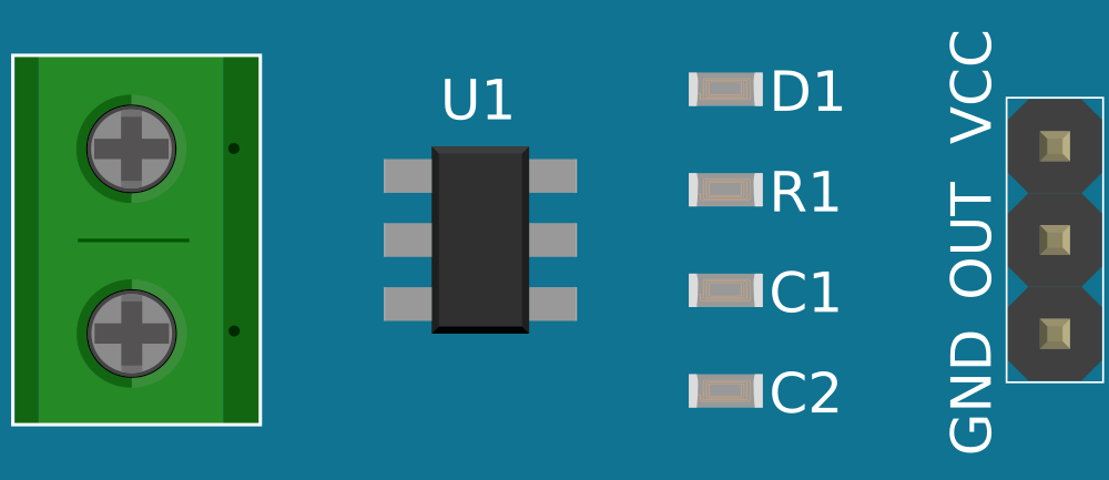
Pin Configuration and Descriptions

Pin Name Description
1 VCC Power supply input (3.3V to 5V). Connect to the positive terminal of the power source.
2 GND Ground connection. Connect to the ground of the circuit.
3 OUT Analog output signal. Provides a voltage proportional to the measured current.

Usage Instructions

How to Use the Current Sensor 5A in a Circuit

  1. Power the Sensor: Connect the VCC pin to a 3.3V or 5V power source and the GND pin to the ground of your circuit.
  2. Connect the Load: Pass the wire carrying the current to be measured through the sensor's sensing loop or terminals (depending on the sensor type).
  3. Read the Output: The OUT pin provides an analog voltage proportional to the current flowing through the sensor. This output can be read using an analog-to-digital converter (ADC) on a microcontroller, such as an Arduino.

Important Considerations and Best Practices

  • Ensure the current flowing through the sensor does not exceed the ±5A limit to avoid damage or inaccurate readings.
  • Use proper insulation and wiring to prevent short circuits or electrical hazards.
  • Place the sensor away from strong magnetic fields, as they may interfere with its accuracy.
  • Calibrate the sensor if precise measurements are required, especially in critical applications.

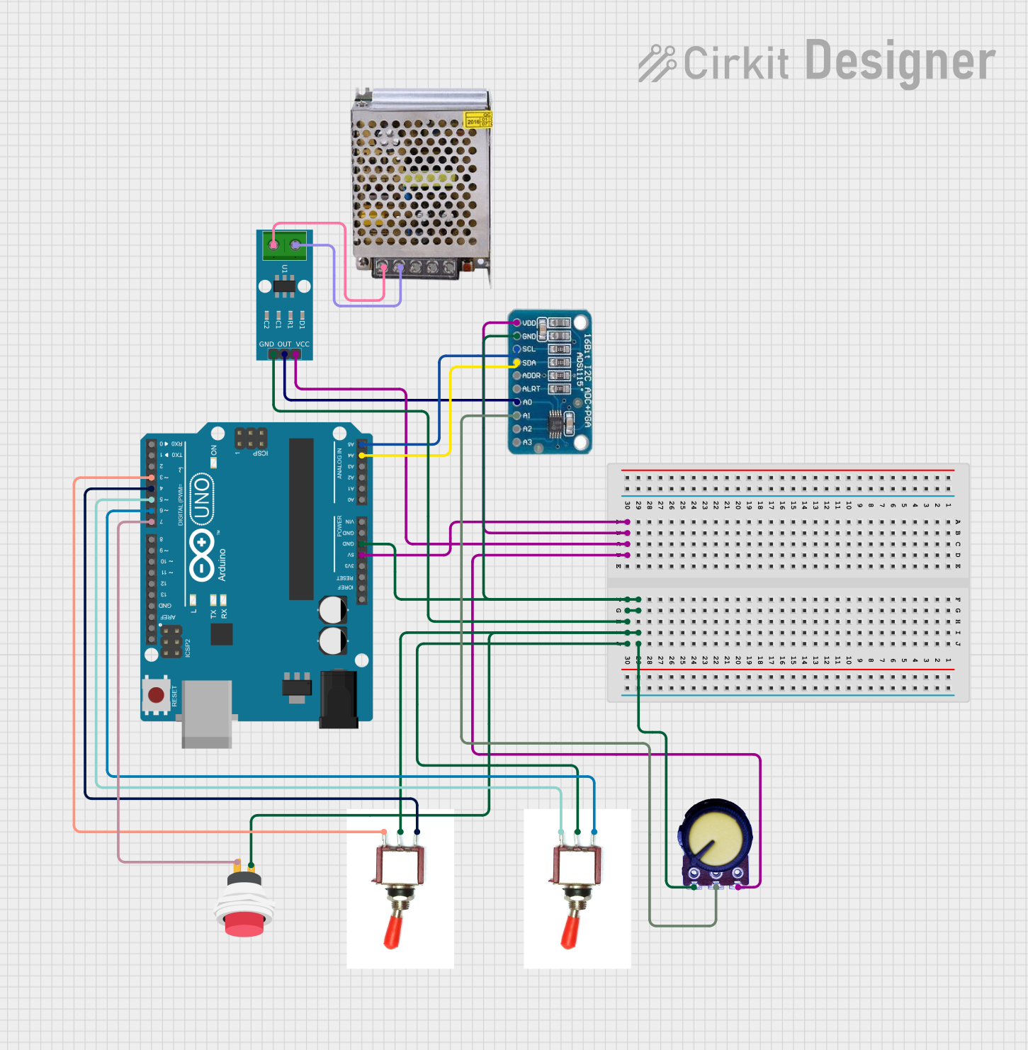
Example: Connecting the Current Sensor 5A to an Arduino UNO

Below is an example of how to use the Current Sensor 5A with an Arduino UNO to measure current and display the readings in the Serial Monitor.

// Example code for using the Current Sensor 5A with Arduino UNO
// This code reads the analog output of the sensor and calculates the current

const int sensorPin = A0; // Connect the OUT pin of the sensor to Arduino A0
const float sensitivity = 0.185; // Sensitivity in V/A (varies by sensor model)
const float offsetVoltage = 2.5; // Offset voltage at 0A (for a 5V-powered sensor)

void setup() {
  Serial.begin(9600); // Initialize Serial Monitor at 9600 baud rate
  pinMode(sensorPin, INPUT); // Set the sensor pin as input
}

void loop() {
  int sensorValue = analogRead(sensorPin); // Read the analog value from the sensor
  float voltage = sensorValue * (5.0 / 1023.0); // Convert ADC value to voltage
  float current = (voltage - offsetVoltage) / sensitivity; // Calculate current in Amperes

  Serial.print("Current: ");
  Serial.print(current, 2); // Print current with 2 decimal places
  Serial.println(" A"); // Append unit (Amperes)

  delay(500); // Wait for 500ms before the next reading
}

Notes:

  • Adjust the sensitivity and offsetVoltage values based on the specific sensor model you are using.
  • Ensure the Arduino is powered properly and shares a common ground with the sensor.

Troubleshooting and FAQs

Common Issues

  1. No Output or Incorrect Readings:

    • Check the wiring connections, ensuring VCC, GND, and OUT are properly connected.
    • Verify that the current flowing through the sensor is within the ±5A range.
  2. Fluctuating or Noisy Readings:

    • Use decoupling capacitors (e.g., 0.1µF) between VCC and GND to stabilize the power supply.
    • Ensure the sensor is not placed near sources of electromagnetic interference.
  3. Output Voltage Does Not Match Expected Values:

    • Confirm the sensor's sensitivity and offset voltage values match the datasheet specifications.
    • Calibrate the sensor by measuring a known current and adjusting calculations accordingly.

FAQs

Q: Can this sensor measure both AC and DC currents?
A: Yes, the Current Sensor 5A can measure both AC and DC currents, but ensure the output signal is interpreted correctly for AC measurements.

Q: How do I calibrate the sensor?
A: Pass a known current through the sensor, measure the output voltage, and adjust the sensitivity and offset values in your calculations to match the actual current.

Q: What happens if the current exceeds 5A?
A: Exceeding the 5A limit may damage the sensor or result in inaccurate readings. Use a higher-rated sensor for larger currents.

Q: Can I use this sensor with a 3.3V microcontroller?
A: Yes, the sensor operates at 3.3V, but ensure the output voltage range is compatible with the ADC of your microcontroller.