
How to Use Adafruit MCP9601: Examples, Pinouts, and Specs
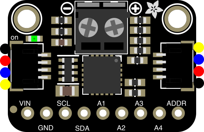
 Design with Adafruit MCP9601 in Cirkit Designer
Introduction
The Adafruit MCP9601 (Manufacturer Part ID: 5165) is a high-precision I2C temperature sensor designed for accurate temperature measurement in a wide range of applications. It supports temperatures from -40°C to +125°C with a resolution of 0.0625°C. The MCP9601 also features an onboard thermocouple interface, making it ideal for projects requiring precise thermal monitoring and control.
Explore Projects Built with Adafruit MCP9601
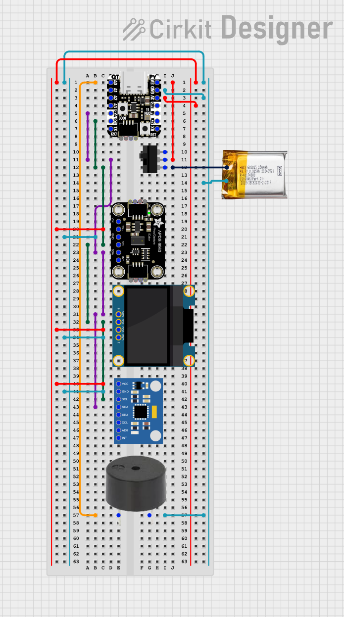 Open Project in Cirkit Designer
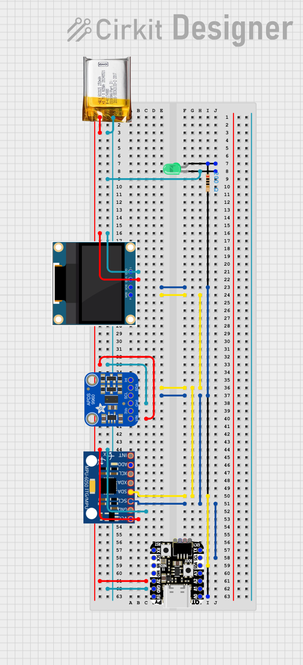 Open Project in Cirkit Designer
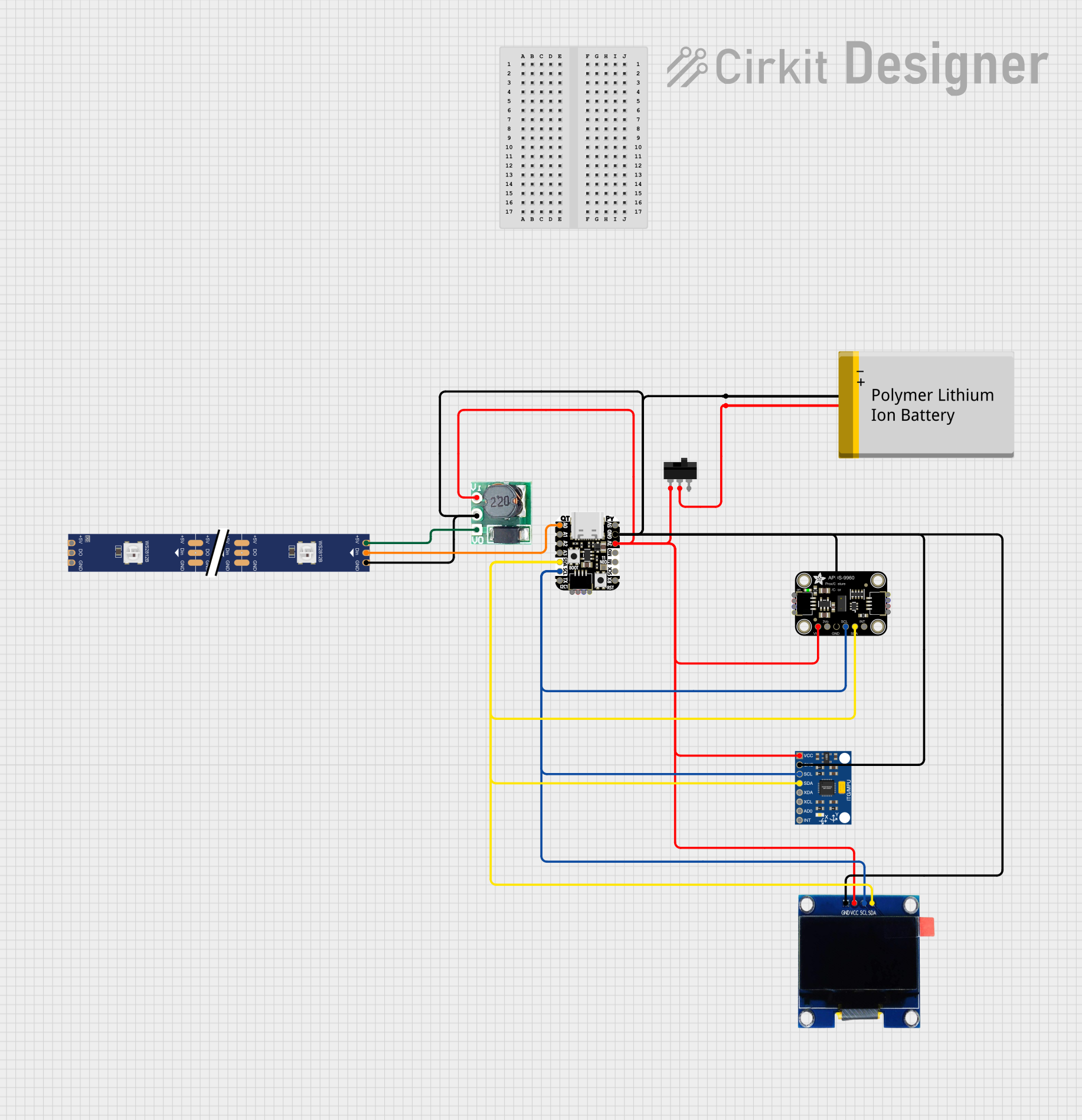 Open Project in Cirkit Designer
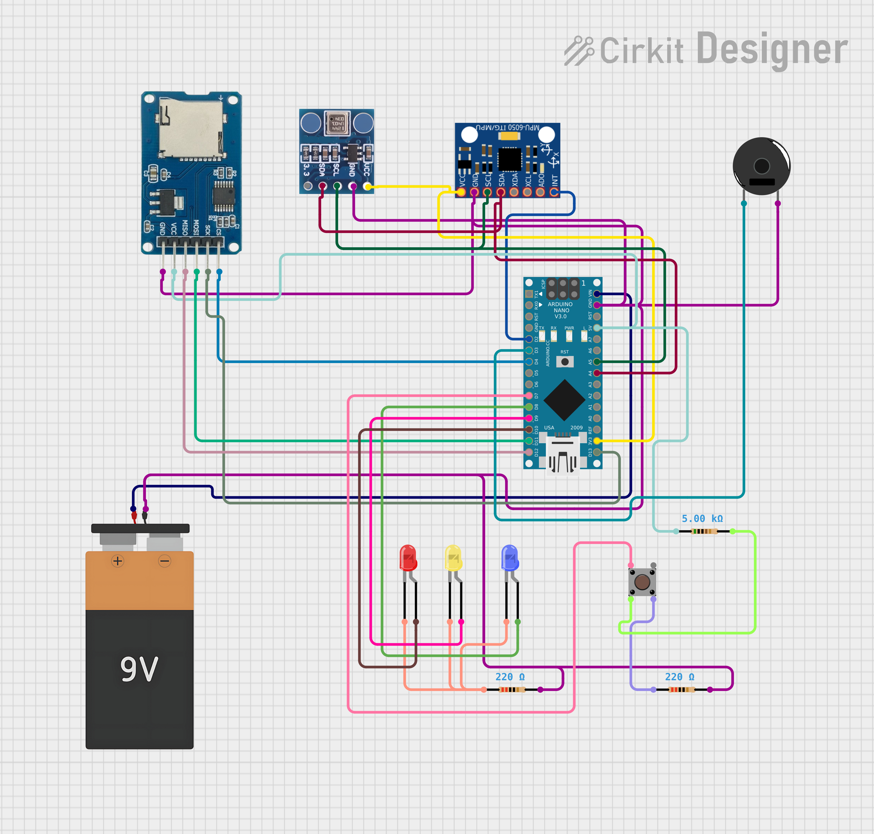 Open Project in Cirkit Designer
Explore Projects Built with Adafruit MCP9601
Open Project in Cirkit DesignerOpen Project in Cirkit DesignerOpen Project in Cirkit DesignerOpen Project in Cirkit DesignerCommon Applications
- Industrial temperature monitoring
- HVAC systems
- Environmental sensing
- IoT devices
- Scientific experiments and data logging
Technical Specifications
The following table outlines the key technical details of the Adafruit MCP9601:
| Parameter | Value |
|---|---|
| Operating Voltage | 3.3V to 5V |
| Temperature Range | -40°C to +125°C |
| Temperature Resolution | 0.0625°C |
| Communication Protocol | I2C |
| I2C Address (Default) | 0x67 |
| Thermocouple Support | Type K, J, T, N, S, E, B, R |
| Current Consumption | ~300 µA (typical) |
| Dimensions | 25mm x 17mm x 3mm |
Pin Configuration
The MCP9601 breakout board has the following pin layout:
| Pin | Name | Description |
|---|---|---|
| 1 | VIN | Power input (3.3V to 5V) |
| 2 | GND | Ground connection |
| 3 | SCL | I2C clock line |
| 4 | SDA | I2C data line |
| 5 | ALERT | Interrupt output for temperature threshold alerts (optional, open-drain output) |
Usage Instructions
Connecting the MCP9601 to a Circuit
- Power Supply: Connect the VIN pin to a 3.3V or 5V power source and the GND pin to ground.
- I2C Communication: Connect the SCL and SDA pins to the corresponding I2C pins on your microcontroller. Use pull-up resistors (typically 4.7kΩ) if your microcontroller does not have internal pull-ups.
- Optional ALERT Pin: If you want to use the temperature threshold alert feature, connect the ALERT pin to a GPIO pin on your microcontroller.
Important Considerations
- Ensure the I2C address (default: 0x67) does not conflict with other devices on the same bus.
- Use a compatible thermocouple type (e.g., Type K) for accurate readings.
- Avoid exposing the sensor to temperatures beyond its specified range (-40°C to +125°C).
Example Code for Arduino UNO
Below is an example of how to use the MCP9601 with an Arduino UNO. This code reads the temperature and prints it to the Serial Monitor.
#include <Wire.h>
#include <Adafruit_MCP9601.h>

// Create an MCP9601 object
Adafruit_MCP9601 mcp;

// Setup function
void setup() {
  Serial.begin(9600); // Initialize serial communication
  while (!Serial) delay(10); // Wait for Serial Monitor to open

  Serial.println("Adafruit MCP9601 Test");

  // Initialize the MCP9601 sensor
  if (!mcp.begin(0x67)) { // Default I2C address is 0x67
    Serial.println("Failed to find MCP9601! Check wiring.");
    while (1);
  }
  Serial.println("MCP9601 found!");
}

// Loop function
void loop() {
  // Read temperature in Celsius
  float temperature = mcp.readThermocoupleTemperature();

  // Print temperature to Serial Monitor
  Serial.print("Temperature: ");
  Serial.print(temperature);
  Serial.println(" °C");

  delay(1000); // Wait 1 second before next reading
}
Notes:
- Install the Adafruit MCP9601 library from the Arduino Library Manager before running the code.
- Ensure proper wiring between the MCP9601 and Arduino UNO.
Troubleshooting and FAQs
Common Issues
Sensor Not Detected
- Cause: Incorrect wiring or I2C address mismatch.
- Solution: Verify the connections and ensure the I2C address matches the one in your code.
Inaccurate Temperature Readings
- Cause: Using an incompatible thermocouple type or poor connections.
- Solution: Ensure the thermocouple type matches the configuration and check for secure connections.
No Output on Serial Monitor
- Cause: Serial Monitor not set to the correct baud rate.
- Solution: Set the Serial Monitor to 9600 baud.
FAQs
Q: Can I use the MCP9601 with a 3.3V microcontroller?
A: Yes, the MCP9601 is compatible with both 3.3V and 5V logic levels.
Q: What thermocouple types are supported?
A: The MCP9601 supports Type K, J, T, N, S, E, B, and R thermocouples.
Q: How do I change the I2C address?
A: The I2C address is fixed at 0x67 for this breakout board. If you need multiple sensors, consider using an I2C multiplexer.
Q: Can I use the ALERT pin for over-temperature warnings?
A: Yes, the ALERT pin can be configured to trigger when the temperature exceeds a set threshold. Refer to the Adafruit MCP9601 library documentation for configuration details.