
How to Use ENCODER_2LED: Examples, Pinouts, and Specs
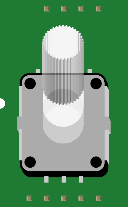
 Design with ENCODER_2LED in Cirkit Designer
Introduction
The ENCODER_2LED is a dual-channel rotary encoder equipped with two LED indicators. This component is widely used for precise position sensing and user input in electronic devices. It converts rotational motion into digital signals, making it ideal for applications such as volume control, menu navigation, and motor position feedback. The integrated LEDs provide visual feedback, enhancing user interaction and debugging.
Explore Projects Built with ENCODER_2LED
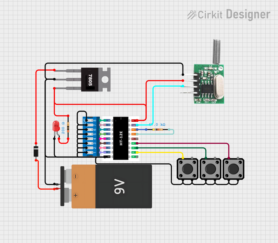 Open Project in Cirkit Designer
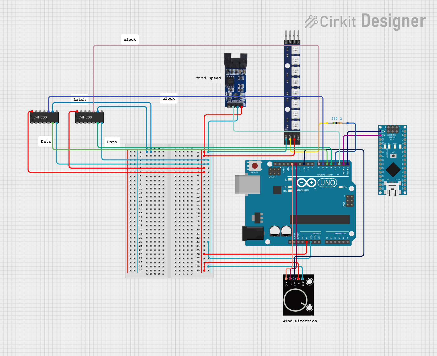 Open Project in Cirkit Designer
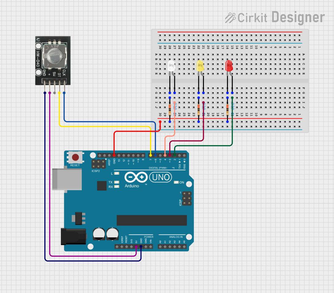 Open Project in Cirkit Designer
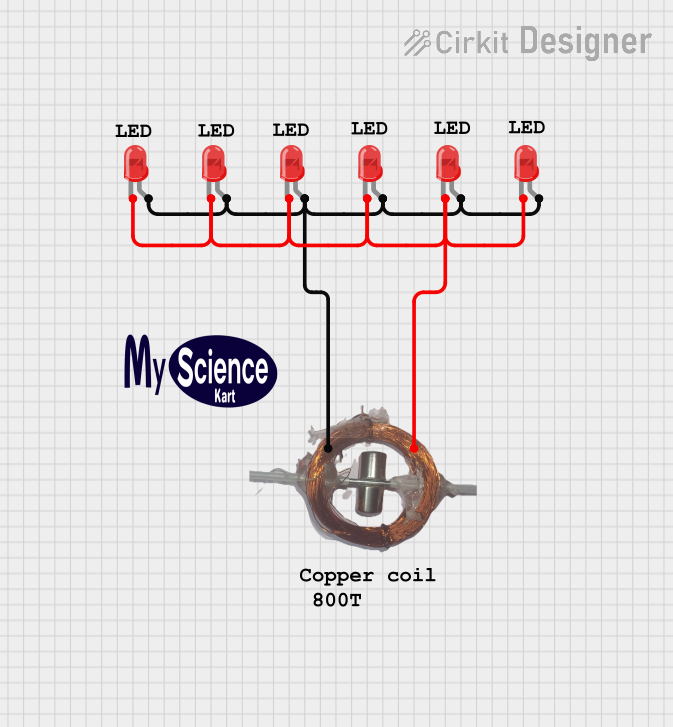 Open Project in Cirkit Designer
Explore Projects Built with ENCODER_2LED
Open Project in Cirkit DesignerOpen Project in Cirkit DesignerOpen Project in Cirkit DesignerOpen Project in Cirkit DesignerTechnical Specifications
- Type: Incremental rotary encoder with dual-channel output (A and B)
- Supply Voltage: 3.3V to 5V DC
- Output Type: Digital (Quadrature signals)
- Resolution: 20 pulses per revolution (PPR)
- LED Indicators: 2 (Red and Green)
- Operating Temperature: -20°C to 70°C
- Mounting: PCB through-hole or panel mount
Pin Configuration and Descriptions
| Pin | Name | Description |
|---|---|---|
| 1 | GND | Ground connection |
| 2 | VCC | Power supply (3.3V to 5V DC) |
| 3 | A | Channel A output signal (digital pulse) |
| 4 | B | Channel B output signal (digital pulse, 90° phase shift from Channel A) |
| 5 | SW | Push-button switch output (active low) |
| 6 | LED_R | Red LED control pin (active high) |
| 7 | LED_G | Green LED control pin (active high) |
Usage Instructions
How to Use the ENCODER_2LED in a Circuit
- Power Connection: Connect the VCC pin to a 3.3V or 5V power source and the GND pin to ground.
- Signal Outputs: Connect the A and B pins to digital input pins on your microcontroller. These pins provide quadrature signals for detecting rotation direction and position.
- Push-Button: The SW pin outputs a digital signal when the encoder's push-button is pressed. Pull this pin high using a resistor (e.g., 10kΩ) if not already integrated into your circuit.
- LED Control: Use the LED_R and LED_G pins to control the red and green LEDs. These can be connected to GPIO pins on a microcontroller for visual feedback.
Important Considerations and Best Practices
- Debouncing: Rotary encoders often produce noisy signals. Use hardware (capacitors) or software (debouncing algorithms) to filter out noise.
- Pull-Up Resistors: Ensure pull-up resistors are used for the SW pin if not already included in your circuit.
- LED Current Limiting: Add appropriate resistors (e.g., 220Ω) in series with the LED_R and LED_G pins to limit current and prevent damage to the LEDs.
- Quadrature Decoding: Use a microcontroller or dedicated IC to decode the quadrature signals from the A and B pins for accurate position tracking.
Example Code for Arduino UNO
// ENCODER_2LED Example Code for Arduino UNO
// This code reads the rotary encoder's position and controls the LEDs.

#define PIN_A 2       // Channel A connected to digital pin 2
#define PIN_B 3       // Channel B connected to digital pin 3
#define PIN_SW 4      // Push-button connected to digital pin 4
#define LED_R 5       // Red LED connected to digital pin 5
#define LED_G 6       // Green LED connected to digital pin 6

volatile int encoderPosition = 0; // Tracks the encoder's position
volatile bool lastAState;         // Stores the last state of Channel A

void setup() {
  pinMode(PIN_A, INPUT);
  pinMode(PIN_B, INPUT);
  pinMode(PIN_SW, INPUT_PULLUP);  // Enable internal pull-up resistor
  pinMode(LED_R, OUTPUT);
  pinMode(LED_G, OUTPUT);

  // Attach interrupt to Channel A for position tracking
  attachInterrupt(digitalPinToInterrupt(PIN_A), readEncoder, CHANGE);

  // Initialize the last state of Channel A
  lastAState = digitalRead(PIN_A);

  Serial.begin(9600); // Initialize serial communication for debugging
}

void loop() {
  // Check if the push-button is pressed
  if (digitalRead(PIN_SW) == LOW) {
    digitalWrite(LED_R, HIGH); // Turn on red LED
    digitalWrite(LED_G, LOW);  // Turn off green LED
  } else {
    digitalWrite(LED_R, LOW);  // Turn off red LED
    digitalWrite(LED_G, HIGH); // Turn on green LED
  }

  // Print the encoder position to the Serial Monitor
  Serial.println(encoderPosition);
  delay(100); // Small delay for readability
}

// Interrupt service routine to read the encoder
void readEncoder() {
  bool currentAState = digitalRead(PIN_A);
  bool currentBState = digitalRead(PIN_B);

  // Determine rotation direction based on quadrature signals
  if (currentAState != lastAState) {
    if (currentAState == currentBState) {
      encoderPosition++; // Clockwise rotation
    } else {
      encoderPosition--; // Counterclockwise rotation
    }
  }

  lastAState = currentAState; // Update the last state of Channel A
}
Troubleshooting and FAQs
Common Issues
No Signal from Encoder:
- Ensure the VCC and GND pins are properly connected.
- Verify that the A and B pins are connected to the correct microcontroller pins.
- Check for loose or damaged wiring.
LEDs Not Lighting Up:
- Confirm that the LED_R and LED_G pins are connected to GPIO pins.
- Check the current-limiting resistors for proper values (e.g., 220Ω).
- Ensure the microcontroller is driving the pins high to activate the LEDs.
Inconsistent or Noisy Signals:
- Add hardware debouncing (e.g., capacitors) or implement software debouncing.
- Verify that the encoder is not subjected to excessive mechanical vibration.
Push-Button Not Responding:
- Check the pull-up resistor on the SW pin.
- Ensure the SW pin is connected to a digital input pin on the microcontroller.
FAQs
Q: Can the ENCODER_2LED work with 3.3V systems?
A: Yes, the encoder is compatible with both 3.3V and 5V systems.Q: How do I calculate the resolution of the encoder?
A: The resolution is 20 pulses per revolution (PPR). For quadrature decoding, this translates to 80 steps per revolution (4x decoding).Q: Can I use the LEDs for other purposes?
A: Yes, the LEDs can be controlled independently via the LED_R and LED_G pins for custom applications.Q: Is the encoder suitable for high-speed applications?
A: The ENCODER_2LED is designed for low to moderate-speed applications. For high-speed use, ensure proper signal conditioning and decoding.