How to Use Logic level switcher: Examples, Pinouts, and Specs
Introduction
A logic level switcher is an essential electronic component designed to enable communication between devices operating at different voltage levels. It acts as a bidirectional voltage translator, ensuring compatibility between components such as microcontrollers, sensors, and modules that use different logic levels (e.g., 3.3V and 5V).
Explore Projects Built with Logic level switcher


Explore Projects Built with Logic level switcher
Common Applications and Use Cases
- Interfacing 3.3V microcontrollers (e.g., ESP32, Raspberry Pi) with 5V peripherals (e.g., Arduino, sensors).
- Bridging communication between I2C, SPI, or UART devices with mismatched voltage levels.
- Protecting low-voltage devices from damage caused by higher voltage signals.
- Enabling mixed-voltage systems in IoT, robotics, and embedded applications.
Technical Specifications
Below are the key technical details of a typical logic level switcher:
| Parameter | Value |
|---|---|
| Operating Voltage | 1.8V to 6V (low side), 2.5V to 18V (high side) |
| Logic Level Support | 1.8V, 3.3V, 5V, and higher |
| Current Handling | Up to 50mA per channel |
| Channels | 2, 4, or 8 channels (depending on model) |
| Communication Types | I2C, SPI, UART, GPIO |
| Bidirectional Support | Yes |
| Operating Temperature | -40°C to +85°C |
Pin Configuration and Descriptions
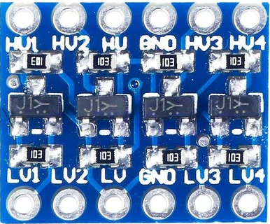
The pinout of a 4-channel logic level switcher is as follows:
| Pin Name | Description |
|---|---|
| HV (High Voltage) | High-side voltage input (e.g., 5V). Connect to the higher voltage logic level. |
| LV (Low Voltage) | Low-side voltage input (e.g., 3.3V). Connect to the lower voltage logic level. |
| GND | Ground. Connect to the ground of both voltage domains. |
| TX1, TX2, TX3, TX4 | High-side signal pins for channels 1 to 4. |
| RX1, RX2, RX3, RX4 | Low-side signal pins for channels 1 to 4. |
Usage Instructions
How to Use the Component in a Circuit
Power Connections:
- Connect the HV pin to the higher voltage logic level (e.g., 5V).
- Connect the LV pin to the lower voltage logic level (e.g., 3.3V).
- Ensure both devices share a common ground by connecting their GND pins.
Signal Connections:
- Connect the high-voltage signal lines to the TX pins (e.g., TX1, TX2).
- Connect the low-voltage signal lines to the corresponding RX pins (e.g., RX1, RX2).
- For bidirectional communication, the logic level switcher will automatically translate signals in both directions.
Verify Voltage Levels:
- Ensure the voltage levels on HV and LV match the operating requirements of the connected devices.
Important Considerations and Best Practices
- Voltage Compatibility: Double-check the voltage levels of your devices to avoid damage.
- Current Limitations: Do not exceed the current rating of the logic level switcher (typically 50mA per channel).
- Pull-Up Resistors: For I2C communication, ensure appropriate pull-up resistors are used on both the high and low sides.
- Noise Reduction: Keep signal wires short to minimize noise and interference.
Example: Connecting to an Arduino UNO
Below is an example of using a logic level switcher to connect a 3.3V sensor to a 5V Arduino UNO via I2C:
Circuit Diagram
- HV: Connect to Arduino's 5V pin.
- LV: Connect to the sensor's 3.3V pin.
- GND: Connect to the common ground of Arduino and the sensor.
- TX1/RX1: Connect to Arduino's SDA pin and the sensor's SDA pin.
- TX2/RX2: Connect to Arduino's SCL pin and the sensor's SCL pin.
Arduino Code Example
#include <Wire.h> // Include the Wire library for I2C communication

void setup() {
  Wire.begin(); // Initialize I2C communication
  Serial.begin(9600); // Start serial communication for debugging
  Serial.println("I2C communication initialized.");
}

void loop() {
  Wire.beginTransmission(0x40); // Start communication with the sensor at address 0x40
  Wire.write(0x00); // Send a command to the sensor (e.g., read data)
  Wire.endTransmission(); // End the transmission

  Wire.requestFrom(0x40, 2); // Request 2 bytes of data from the sensor
  if (Wire.available() == 2) { // Check if 2 bytes are available
    int data = Wire.read() << 8 | Wire.read(); // Read and combine the 2 bytes
    Serial.print("Sensor Data: ");
    Serial.println(data); // Print the sensor data
  }

  delay(1000); // Wait for 1 second before the next reading
}
Troubleshooting and FAQs
Common Issues and Solutions
No Signal Translation:
- Cause: Incorrect voltage connections or missing ground connection.
- Solution: Verify that HV, LV, and GND are properly connected.
Signal Noise or Instability:
- Cause: Long signal wires or lack of pull-up resistors.
- Solution: Use shorter wires and ensure proper pull-up resistors are in place.
Device Not Responding:
- Cause: Incorrect pin connections or mismatched I2C addresses.
- Solution: Double-check the wiring and ensure the correct I2C address is used in the code.
Overheating:
- Cause: Exceeding the current rating of the logic level switcher.
- Solution: Ensure the current draw of connected devices is within the switcher's limits.
FAQs
Q: Can I use a logic level switcher for SPI communication?
- A: Yes, logic level switchers can be used for SPI communication. Ensure all SPI lines (MOSI, MISO, SCK, CS) are connected through the switcher.
Q: Do I need external pull-up resistors for I2C?
- A: Yes, pull-up resistors are required for I2C communication. Some logic level switchers include built-in pull-up resistors, but external ones may still be needed for optimal performance.
Q: Can I use a logic level switcher with 1.8V devices?
- A: Yes, as long as the switcher supports 1.8V on the low side. Check the datasheet for compatibility.
By following this documentation, you can effectively use a logic level switcher to bridge voltage gaps between devices and ensure seamless communication in your projects.