How to Use HiLetgo 3.5" TFT LCD Display ILI9486/ILI9488 480x320 36 Pin: Examples, Pinouts, and Specs
Introduction
The HiLetgo 3.5" TFT LCD Display is a high-quality display module designed for embedded systems and microcontroller-based projects. It features a 3.5-inch screen with a resolution of 480x320 pixels, providing clear and vibrant visuals. The display is powered by the ILI9486 or ILI9488 driver IC, which supports a wide range of color formats and graphical functions. Its 36-pin interface allows for straightforward integration with microcontrollers, making it ideal for applications such as graphical user interfaces, data visualization, and portable devices.
Explore Projects Built with HiLetgo 3.5" TFT LCD Display ILI9486/ILI9488 480x320 36 Pin


Explore Projects Built with HiLetgo 3.5" TFT LCD Display ILI9486/ILI9488 480x320 36 Pin
Common Applications and Use Cases
- Graphical user interfaces for embedded systems
- Data visualization in IoT projects
- Portable devices and handheld instruments
- Educational projects and prototyping
- Industrial control panels and dashboards
Technical Specifications
Below are the key technical details of the HiLetgo 3.5" TFT LCD Display:
| Specification | Details |
|---|---|
| Display Type | TFT LCD |
| Screen Size | 3.5 inches |
| Resolution | 480x320 pixels |
| Driver IC | ILI9486 / ILI9488 |
| Interface | 36-pin parallel interface |
| Operating Voltage | 3.3V (logic level) |
| Backlight Voltage | 5V |
| Color Depth | 16-bit (65,536 colors) |
| Viewing Angle | Wide viewing angle |
| Dimensions | 85mm x 55mm x 3mm |
| Touchscreen Support | No (non-touch display) |
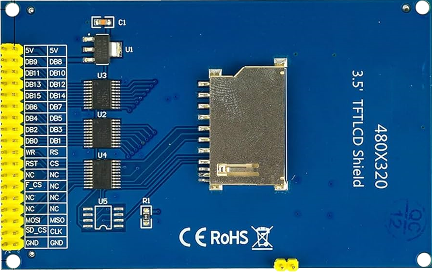
Pin Configuration and Descriptions
The 36-pin interface of the display is detailed in the table below:
| Pin Number | Pin Name | Description |
|---|---|---|
| 1-8 | DB0-DB7 | Data Bus (Lower 8 bits) |
| 9-16 | DB8-DB15 | Data Bus (Upper 8 bits) |
| 17 | RS | Register Select (Command/Data selection) |
| 18 | WR | Write Signal (Active Low) |
| 19 | RD | Read Signal (Active Low) |
| 20 | CS | Chip Select (Active Low) |
| 21 | RESET | Reset Signal (Active Low) |
| 22 | IM0 | Interface Mode Selection |
| 23 | IM1 | Interface Mode Selection |
| 24 | IM2 | Interface Mode Selection |
| 25 | LED+ | Backlight Power (5V) |
| 26 | LED- | Backlight Ground |
| 27-36 | GND/VCC | Ground and Power Supply Pins |
Usage Instructions
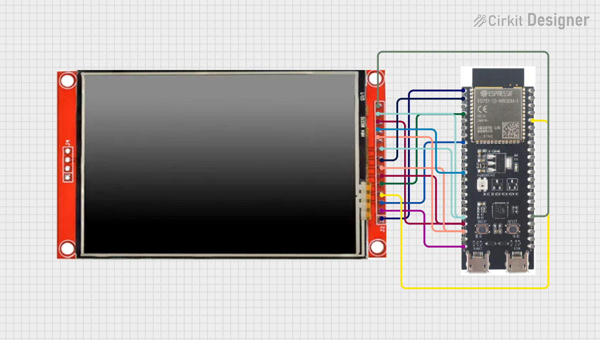
How to Use the Component in a Circuit
- Power Supply: Connect the display's power pins (VCC and GND) to a 3.3V power source for logic and 5V for the backlight.
- Data Bus: Connect the data bus pins (DB0-DB15) to the corresponding microcontroller pins. Ensure the microcontroller supports 16-bit parallel communication.
- Control Pins: Connect the control pins (RS, WR, RD, CS, RESET) to the microcontroller's GPIO pins. These pins manage the display's operation.
- Interface Mode: Configure the IM0, IM1, and IM2 pins to select the desired interface mode. For most microcontrollers, parallel mode is used.
- Backlight: Connect the LED+ pin to a 5V source and the LED- pin to ground to power the backlight.
Important Considerations and Best Practices
- Voltage Levels: Ensure the microcontroller's GPIO pins operate at 3.3V logic levels to avoid damaging the display.
- Initialization: Properly initialize the ILI9486/ILI9488 driver in your code before sending data to the display.
- Decoupling Capacitors: Use decoupling capacitors near the power pins to reduce noise and ensure stable operation.
- Avoid Static Damage: Handle the display carefully to prevent static discharge, which can damage the sensitive components.
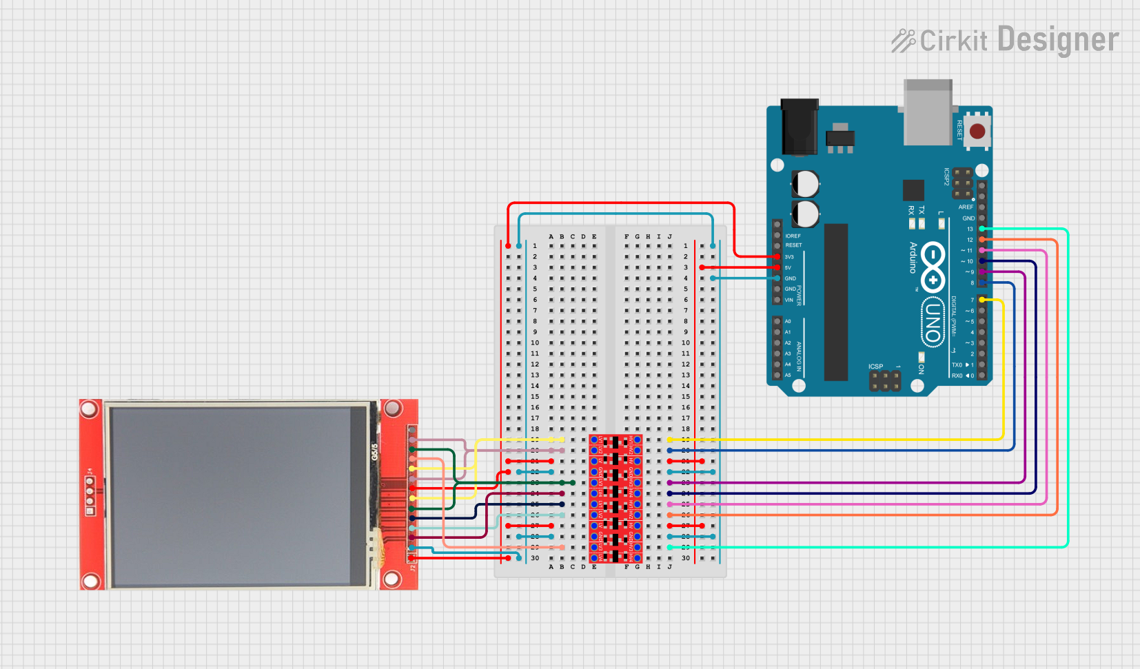
Example Code for Arduino UNO
Below is an example of how to interface the display with an Arduino UNO using the Adafruit GFX and MCUFRIEND_kbv libraries:
#include <Adafruit_GFX.h>       // Graphics library for drawing shapes and text
#include <MCUFRIEND_kbv.h>      // Library for ILI9486/ILI9488 driver

MCUFRIEND_kbv tft;              // Create an instance of the display object

#define BLACK 0x0000            // Define color constants
#define WHITE 0xFFFF
#define RED   0xF800
#define GREEN 0x07E0
#define BLUE  0x001F

void setup() {
  Serial.begin(9600);           // Initialize serial communication
  uint16_t ID = tft.readID();   // Read the display's ID
  if (ID == 0x9486 || ID == 0x9488) {
    Serial.println("Display detected!");
  } else {
    Serial.println("Unknown display ID!");
  }
  tft.begin(ID);                // Initialize the display with the detected ID
  tft.setRotation(1);           // Set display orientation (1 = landscape)
  tft.fillScreen(BLACK);        // Clear the screen with black color
  tft.setTextColor(WHITE);      // Set text color to white
  tft.setTextSize(2);           // Set text size
  tft.setCursor(10, 10);        // Set cursor position
  tft.print("Hello, World!");   // Display text on the screen
}

void loop() {
  // Add your code here to update the display
}
Troubleshooting and FAQs
Common Issues and Solutions
Display Not Turning On:
- Ensure the power supply connections (VCC and GND) are correct.
- Verify that the backlight pins (LED+ and LED-) are properly connected.
No Image or Incorrect Colors:
- Check the data bus connections (DB0-DB15) for loose or incorrect wiring.
- Ensure the control pins (RS, WR, RD, CS, RESET) are correctly connected and configured.
Unknown Display ID:
- Verify that the display is properly powered and connected to the microcontroller.
- Ensure the correct libraries (Adafruit GFX and MCUFRIEND_kbv) are installed and included in your code.
Flickering or Unstable Display:
- Add decoupling capacitors near the power pins to stabilize the voltage supply.
- Check for loose connections or interference from nearby components.
FAQs
Q: Can this display be used with a 5V microcontroller like Arduino UNO?
A: Yes, but you will need level shifters to convert the 5V logic signals to 3.3V to avoid damaging the display.
Q: Does this display support touch input?
A: No, this is a non-touch display. For touch functionality, consider a similar model with a touchscreen.
Q: How do I change the orientation of the display?
A: Use the setRotation() function in your code. Valid values are 0, 1, 2, and 3 for different orientations.
Q: Can I use SPI instead of a parallel interface?
A: No, this display only supports a 36-pin parallel interface. For SPI, consider a different model.