Cirkit Designer
Your all-in-one circuit design IDE
Home /
Component Documentation
How to Use as7263: Examples, Pinouts, and Specs
Introduction
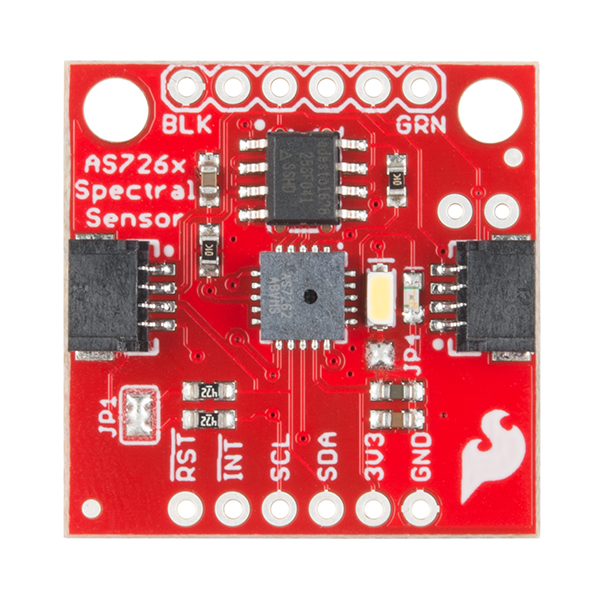
The AS7263 is a 6-channel near-infrared spectral sensor manufactured by SparkFun, with the part ID NIR. This sensor provides digital measurements of light intensity for wavelengths between 610nm and 860nm. It is commonly used in applications such as material and liquid analysis, color matching, and spectral identification.
Explore Projects Built with as7263
Battery-Powered Emergency Alert System with NUCLEO-F072RB, SIM800L, and GPS NEO 6M

This circuit is an emergency alert system that uses a NUCLEO-F072RB microcontroller to send SMS alerts and make calls via a SIM800L GSM module, while obtaining location data from a GPS NEO 6M module. The system is powered by a Li-ion battery and includes a TP4056 module for battery charging and protection, with a rocker switch to control power to the microcontroller.
Arduino UNO and SIM A7670c Based SMS Notification System with Battery Power
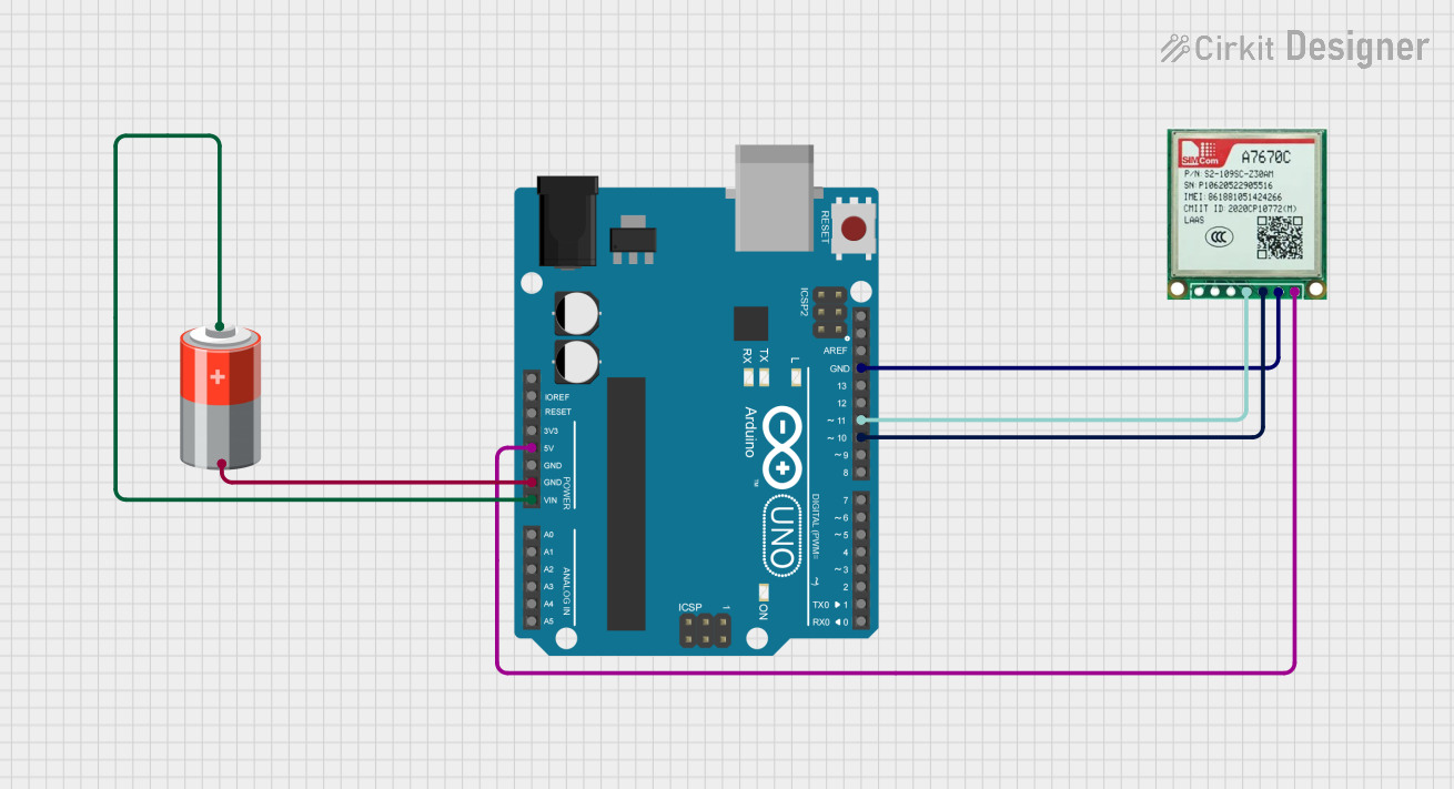
This circuit integrates an Arduino UNO with a Sim A7670c GSM module and a 5V battery to enable SMS communication and control a relay based on input from a switch and a push button. The Arduino handles the logic for sending SMS notifications and toggling the relay, while the GSM module facilitates the SMS functionality.
Satellite-Based Timing and Navigation System with SDR and Atomic Clock Synchronization

This circuit appears to be a complex system involving power supply management, GPS and timing synchronization, and data communication. It includes a SI-TEX G1 Satellite Compass for GPS data, an XHTF1021 Atomic Rubidium Clock for precise timing, and Ettus USRP B200 units for software-defined radio communication. Power is supplied through various SMPS units and distributed via terminal blocks and DC jacks. Data communication is facilitated by Beelink MINI S12 N95 computers, RS232 splitters, and a 1000BASE-T Media Converter for network connectivity. RF Directional Couplers are used to interface antennas with the USRP units, and the entire system is likely contained within cases for protection and organization.
ESP32 and SIM900A Based Smart Home Automation with Wi-Fi and GSM Control
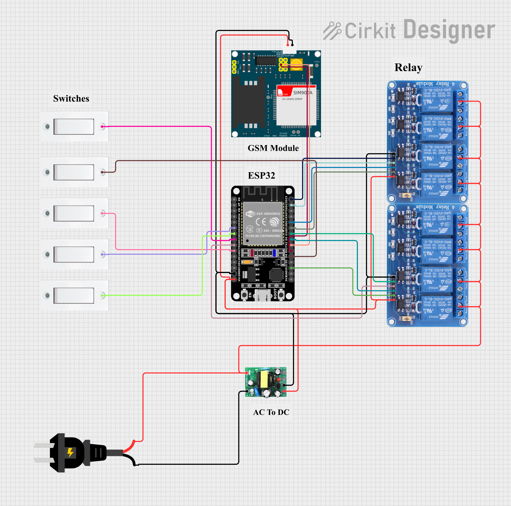
This circuit features an ESP32 microcontroller interfaced with multiple flush switches and two 4-channel relay modules to control various loads. It also includes a SIM900A module for GSM communication and an AC to DC converter for power management. The ESP32 handles input from the switches and controls the relays, while the SIM900A provides remote communication capabilities.
Explore Projects Built with as7263
Battery-Powered Emergency Alert System with NUCLEO-F072RB, SIM800L, and GPS NEO 6M
This circuit is an emergency alert system that uses a NUCLEO-F072RB microcontroller to send SMS alerts and make calls via a SIM800L GSM module, while obtaining location data from a GPS NEO 6M module. The system is powered by a Li-ion battery and includes a TP4056 module for battery charging and protection, with a rocker switch to control power to the microcontroller.
Arduino UNO and SIM A7670c Based SMS Notification System with Battery Power
This circuit integrates an Arduino UNO with a Sim A7670c GSM module and a 5V battery to enable SMS communication and control a relay based on input from a switch and a push button. The Arduino handles the logic for sending SMS notifications and toggling the relay, while the GSM module facilitates the SMS functionality.
Satellite-Based Timing and Navigation System with SDR and Atomic Clock Synchronization
This circuit appears to be a complex system involving power supply management, GPS and timing synchronization, and data communication. It includes a SI-TEX G1 Satellite Compass for GPS data, an XHTF1021 Atomic Rubidium Clock for precise timing, and Ettus USRP B200 units for software-defined radio communication. Power is supplied through various SMPS units and distributed via terminal blocks and DC jacks. Data communication is facilitated by Beelink MINI S12 N95 computers, RS232 splitters, and a 1000BASE-T Media Converter for network connectivity. RF Directional Couplers are used to interface antennas with the USRP units, and the entire system is likely contained within cases for protection and organization.
ESP32 and SIM900A Based Smart Home Automation with Wi-Fi and GSM Control
This circuit features an ESP32 microcontroller interfaced with multiple flush switches and two 4-channel relay modules to control various loads. It also includes a SIM900A module for GSM communication and an AC to DC converter for power management. The ESP32 handles input from the switches and controls the relays, while the SIM900A provides remote communication capabilities.
Technical Specifications
Key Technical Details
| Parameter | Value |
|---|---|
| Supply Voltage | 3.3V |
| Operating Current | 100mA (typical) |
| Spectral Channels | 6 |
| Wavelength Range | 610nm to 860nm |
| Communication | I2C |
| I2C Address | 0x49 |
| Operating Temperature | -40°C to +85°C |
Pin Configuration and Descriptions
| Pin Number | Pin Name | Description |
|---|---|---|
| 1 | GND | Ground |
| 2 | VCC | Supply Voltage (3.3V) |
| 3 | SDA | I2C Data Line |
| 4 | SCL | I2C Clock Line |
| 5 | INT | Interrupt Output (Active Low) |
| 6 | RST | Reset (Active Low) |
Usage Instructions
How to Use the Component in a Circuit
- Power Supply: Connect the VCC pin to a 3.3V power supply and the GND pin to the ground.
- I2C Communication: Connect the SDA pin to the SDA line of your microcontroller and the SCL pin to the SCL line.
- Interrupt and Reset: Optionally, connect the INT pin to an interrupt-capable pin on your microcontroller and the RST pin to a digital output pin for reset functionality.
Important Considerations and Best Practices
- Ensure that the power supply is stable and within the specified range (3.3V).
- Use appropriate pull-up resistors (typically 4.7kΩ) on the I2C lines if they are not already present on your microcontroller.
- Avoid exposing the sensor to direct sunlight or other strong light sources to prevent saturation.
- Calibrate the sensor in your specific application environment for accurate measurements.
Example Code for Arduino UNO
#include <Wire.h>
#include "SparkFun_AS726X.h"

AS726X sensor;

void setup() {
  Serial.begin(9600);
  Wire.begin();

  if (sensor.begin() == false) {
    Serial.println("AS7263 not detected. Check wiring.");
    while (1);
  }

  sensor.setMeasurementMode(2); // Set to 2 for continuous mode
  sensor.enableIndicator(); // Enable the indicator LED
}

void loop() {
  sensor.takeMeasurements();

  Serial.print("610nm: ");
  Serial.println(sensor.getCalibratedA());

  Serial.print("680nm: ");
  Serial.println(sensor.getCalibratedB());

  Serial.print("730nm: ");
  Serial.println(sensor.getCalibratedC());

  Serial.print("760nm: ");
  Serial.println(sensor.getCalibratedD());

  Serial.print("810nm: ");
  Serial.println(sensor.getCalibratedE());

  Serial.print("860nm: ");
  Serial.println(sensor.getCalibratedF());

  delay(1000); // Wait for 1 second before taking new measurements
}
Troubleshooting and FAQs
Common Issues Users Might Face
- Sensor Not Detected: Ensure that the I2C connections (SDA and SCL) are correctly made and that the sensor is powered with 3.3V.
- Incorrect Readings: Verify that the sensor is not exposed to direct sunlight or other strong light sources. Calibrate the sensor in your specific environment.
- No Data Output: Check the serial monitor settings (baud rate) and ensure that the sensor is properly initialized in the code.
Solutions and Tips for Troubleshooting
- Check Connections: Double-check all wiring connections, especially the I2C lines.
- Power Supply: Ensure that the sensor is receiving a stable 3.3V power supply.
- Pull-up Resistors: Make sure that appropriate pull-up resistors are used on the I2C lines.
- Code Verification: Verify that the example code is correctly uploaded to the Arduino and that the serial monitor is set to the correct baud rate (9600 in this case).
By following this documentation, users should be able to effectively integrate and utilize the AS7263 near-infrared spectral sensor in their projects.