How to Use SHTC3: Examples, Pinouts, and Specs

Introduction
The SHTC3 is a high-precision digital sensor capable of measuring relative humidity and temperature. It is designed for high accuracy, low power consumption, and ease of integration, making it ideal for a wide range of applications including weather stations, HVAC systems, consumer electronics, and medical devices. Its small form factor and I2C communication protocol facilitate its use in space-constrained applications.
Explore Projects Built with SHTC3
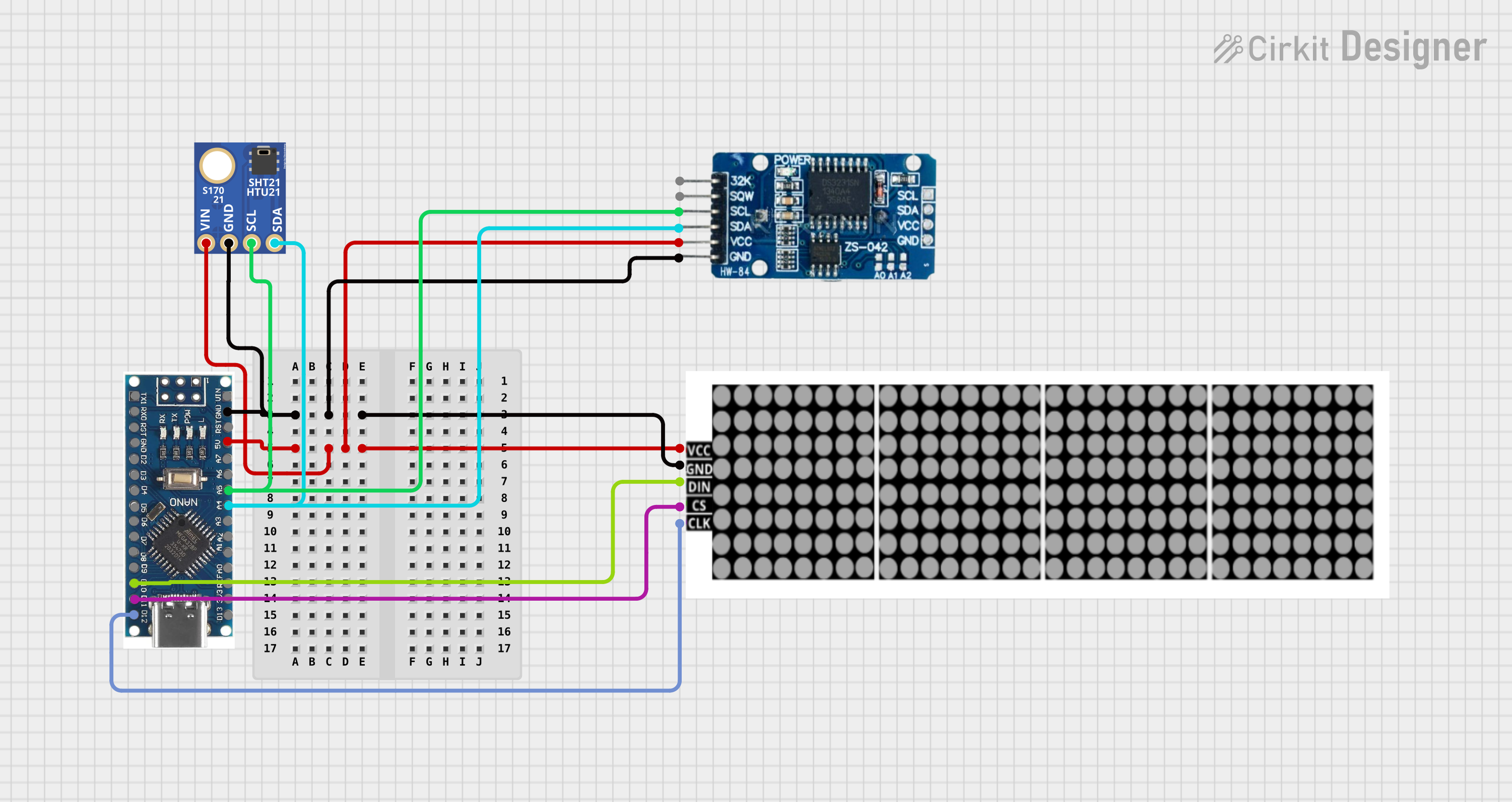
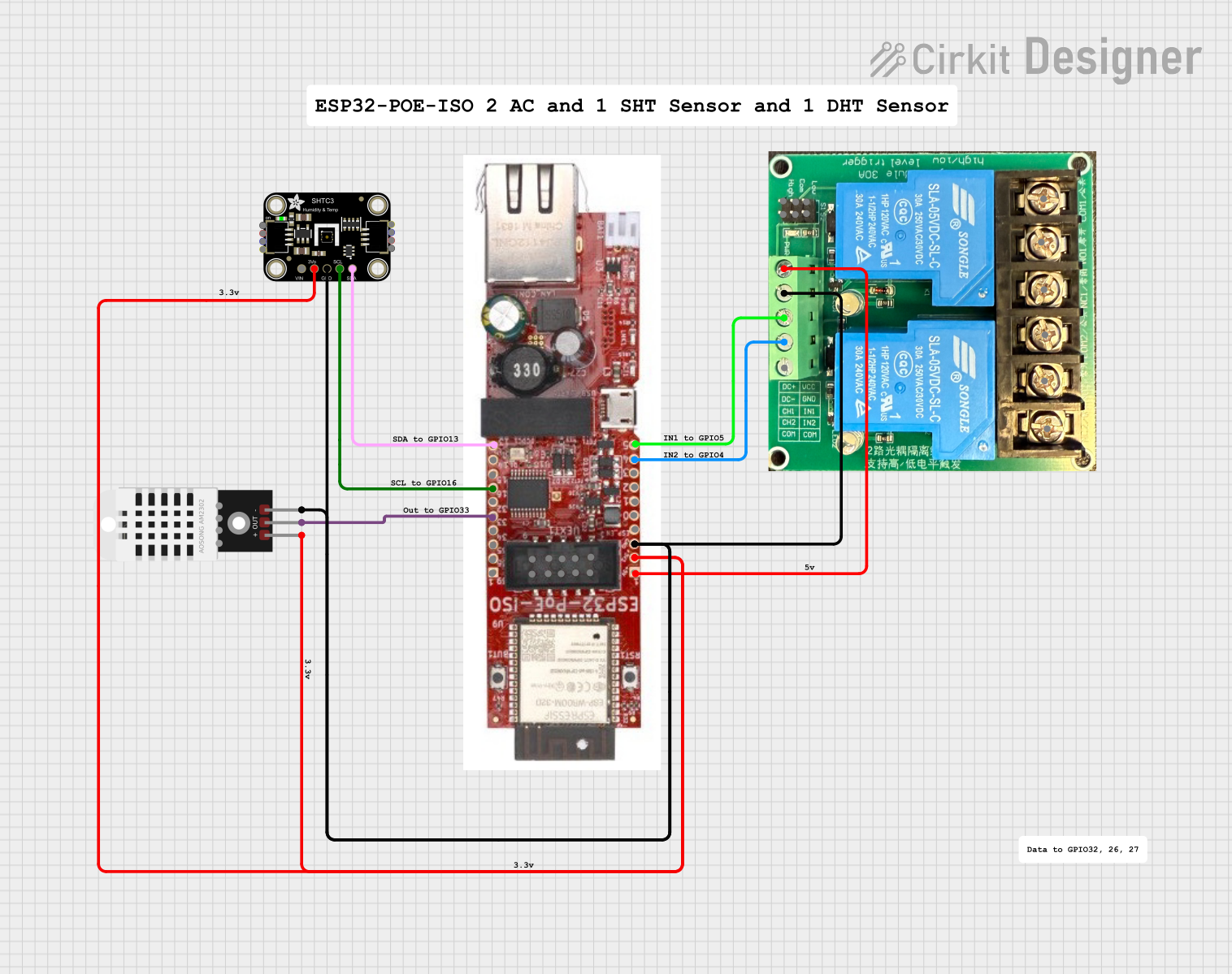


Explore Projects Built with SHTC3
Technical Specifications
Key Technical Details
- Relative Humidity Range: 0 to 100% RH
- Temperature Range: -40°C to 125°C (-40°F to 257°F)
- Humidity Accuracy: ±2% RH (typical)
- Temperature Accuracy: ±0.2°C (typical)
- Supply Voltage: 1.62V to 3.6V
- Current Consumption: 0.4µA (sleep mode), 15µA (average measurement)
- Interface: I2C
- I2C Address: 0x70 (7-bit)
Pin Configuration and Descriptions
| Pin Number | Name | Description |
|---|---|---|
| 1 | VDD | Power supply voltage (1.62V to 3.6V) |
| 2 | GND | Ground reference for the power supply |
| 3 | SDA | Serial Data Line for I2C communication |
| 4 | SCL | Serial Clock Line for I2C communication |
| 5 | NC | No Connection (do not connect) |
Usage Instructions
Integration into a Circuit
- Connect the VDD pin to a power supply within the range of 1.62V to 3.6V.
- Connect the GND pin to the ground of the power supply.
- Connect the SDA and SCL pins to the corresponding I2C data and clock lines on your microcontroller, such as an Arduino UNO.
- If necessary, use pull-up resistors on the SDA and SCL lines as per the I2C standard.
Best Practices
- Ensure that the power supply is stable and within the specified voltage range.
- Keep the sensor away from direct sunlight and sources of heat or moisture that could affect its readings.
- Use appropriate decoupling capacitors close to the sensor to minimize power supply noise.
- Avoid physical stress and contamination during handling and operation.
Example Code for Arduino UNO
#include <Wire.h>
#include <SHTC3.h>

SHTC3 shtc3(Wire);

void setup() {
  Serial.begin(9600);
  Wire.begin();
  shtc3.begin();
}

void loop() {
  if (shtc3.read()) {
    Serial.print("Temperature: ");
    Serial.print(shtc3.getTemperature(), 2);
    Serial.println("°C");
    Serial.print("Humidity: ");
    Serial.print(shtc3.getHumidity(), 2);
    Serial.println("%");
  } else {
    Serial.println("Sensor read failed!");
  }
  delay(1000); // Wait for 1 second between readings
}
Troubleshooting and FAQs
Common Issues
- Sensor not responding: Ensure that the I2C address is correct and that the SDA and SCL lines are properly connected with pull-up resistors.
- Inaccurate readings: Verify that the sensor is not exposed to heat sources or direct sunlight and that it has been given enough time to acclimatize to the environment.
- Noisy data: Check the power supply for stability and use decoupling capacitors as needed.
FAQs
Q: Can the SHTC3 sensor be used with a 5V system? A: The SHTC3 is rated for a maximum of 3.6V. A level shifter or voltage regulator is required to interface with a 5V system.
Q: How long does the sensor need to stabilize before providing accurate readings? A: The sensor typically requires a few seconds to stabilize after power-up. Refer to the datasheet for specific timing information.
Q: Is the SHTC3 waterproof? A: No, the SHTC3 is not waterproof. It should be protected from direct contact with water or other liquids.
Q: How can I calibrate the sensor? A: The SHTC3 comes factory-calibrated. However, for critical applications, you may perform additional calibration using a reference humidity and temperature source.
This documentation provides a comprehensive guide to the SHTC3 sensor, ensuring users can effectively integrate and utilize this component in their projects. For further details, consult the manufacturer's datasheet.