How to Use Heltec LoRa V2: Examples, Pinouts, and Specs
Introduction
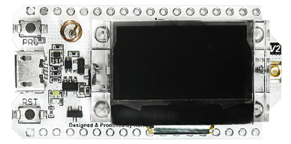
The Heltec LoRa V2 is a versatile and powerful development board designed for long-range wireless communication applications. It integrates an OLED display and a LoRa transceiver, making it ideal for IoT projects and remote sensor networks. The board is compatible with the Arduino IDE, which allows for easy programming and deployment of custom applications.
Explore Projects Built with Heltec LoRa V2
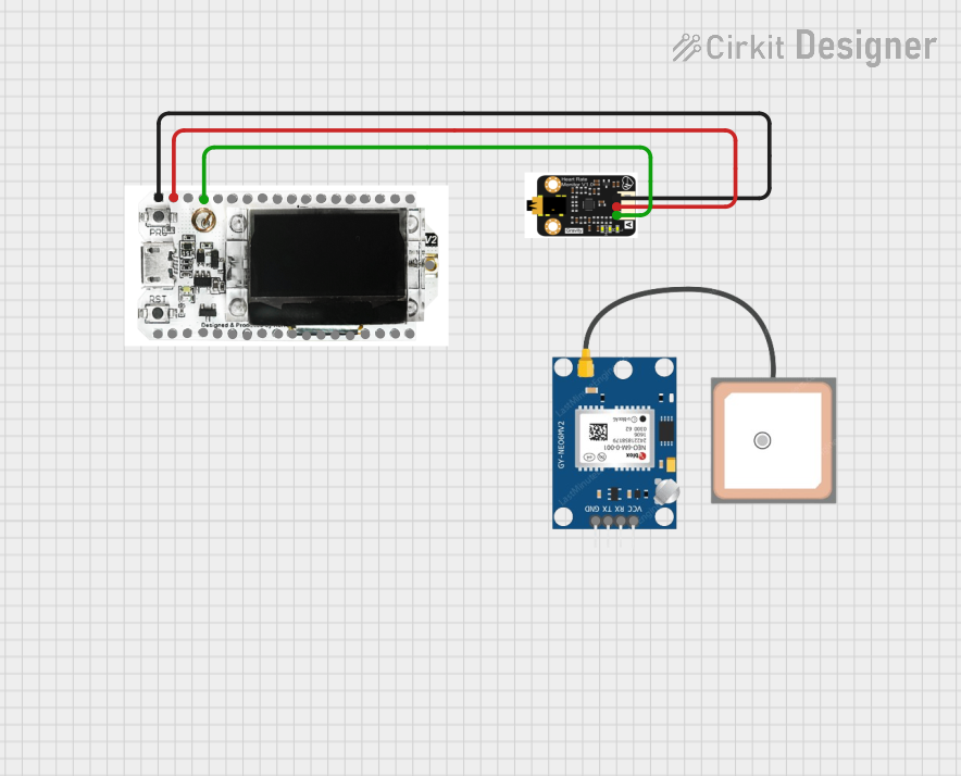
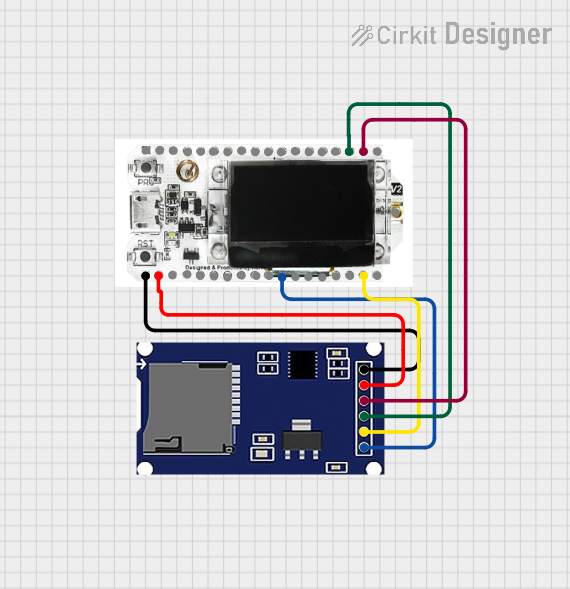

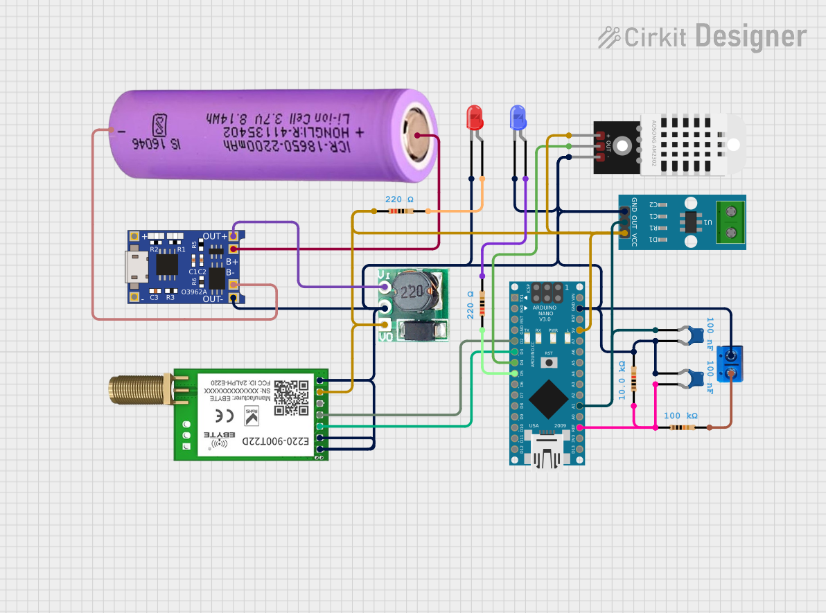
Explore Projects Built with Heltec LoRa V2
Common Applications and Use Cases
- Remote environmental monitoring
- Home automation networks
- Agricultural monitoring systems
- Asset tracking and logistics
- Smart city infrastructure
Technical Specifications
Key Technical Details
- Microcontroller: ESP32
- Operating Voltage: 3.3V
- Input Voltage (recommended): 5V via USB or 7-12V via VIN pin
- Digital I/O Pins: 22
- Analog Input Pins: 6 (ADC channels)
- Clock Speed: 240 MHz
- Flash Memory: 4 MB
- SRAM: 520 KB
- LoRa Chip: SX1276
- Frequency Range: 868/915 MHz (depending on the model)
- Max Transmit Power: +20 dBm
- Sensitivity: down to -148 dBm
- OLED Display: 0.96 inch, 128x64 pixels
Pin Configuration and Descriptions
| Pin Number | Function | Description |
|---|---|---|
| 1 | GND | Ground |
| 2 | 3V3 | 3.3V power supply |
| 3 | 5V | 5V power supply (USB or VIN) |
| 4 | VIN | Input voltage for battery or external power |
| 5 | RST | Reset pin |
| 6 | 3V3 | 3.3V output from the onboard voltage regulator |
| ... | ... | ... |
| 21 | SDA (OLED) | I2C Data for OLED display |
| 22 | SCL (OLED) | I2C Clock for OLED display |
| 23 | MISO (LoRa) | SPI MISO for LoRa transceiver |
| 24 | MOSI (LoRa) | SPI MOSI for LoRa transceiver |
| 25 | SCK (LoRa) | SPI Clock for LoRa transceiver |
| 26 | NSS (LoRa) | SPI Chip Select for LoRa transceiver |
| 27 | DIO0 (LoRa) | LoRa DIO0 interrupt pin |
| 28 | DIO1 (LoRa) | LoRa DIO1 interrupt pin |
| ... | ... | ... |
Note: This is a partial list. Refer to the Heltec LoRa V2 datasheet for the complete pinout.
Usage Instructions
How to Use the Component in a Circuit
- Powering the Board:
- Connect the USB cable to the board and your computer or use an external power source connected to the VIN pin.
- Programming the Board:
- Install the required board support package in the Arduino IDE.
- Select the Heltec LoRa V2 board from the Tools > Board menu.
- Write your sketch and upload it to the board using the onboard USB port.
- Connecting the LoRa Antenna:
- Attach the provided LoRa antenna to the appropriate U.FL connector on the board.
- Using the OLED Display:
- Utilize the onboard I2C interface to communicate with the OLED display.
Important Considerations and Best Practices
- Always attach the LoRa antenna before powering the board to avoid damaging the LoRa transceiver.
- Ensure that the power supply is within the recommended voltage range to prevent damage to the board.
- When using battery power, monitor the voltage to prevent deep discharge.
Troubleshooting and FAQs
Common Issues
- Board not recognized by the computer:
- Check the USB cable and port.
- Ensure the correct drivers are installed.
- LoRa communication failure:
- Verify that the antenna is properly connected.
- Check the frequency settings in your code to match your regional LoRaWAN frequency plan.
- OLED display not working:
- Confirm that the I2C pins are correctly defined in your sketch.
- Check for proper power supply to the OLED circuit.
Solutions and Tips for Troubleshooting
- If the board is not recognized, try a different USB cable or port, and reset the board.
- For LoRa issues, ensure that you are within the range of the receiver and that there are no obstructions.
- For OLED issues, use example sketches to test the display independently.
FAQs
Q: Can I use the Heltec LoRa V2 with a battery? A: Yes, you can power the board with a battery connected to the VIN pin.
Q: What is the range of the LoRa communication? A: The range can vary from a few kilometers in urban areas to over 10 kilometers in open rural areas.
Q: How do I program the OLED display?
A: You can use libraries such as U8g2 or Adafruit_SSD1306 for Arduino to control the OLED display.
Example Code for Arduino UNO
#include <SPI.h>
#include <LoRa.h>

// Define the pins used by the LoRa transceiver module
#define SCK     5   // GPIO5  -- SX1278's SCK
#define MISO    19  // GPIO19 -- SX1278's MISO
#define MOSI    27  // GPIO27 -- SX1278's MOSI
#define SS      18  // GPIO18 -- SX1278's CS
#define RST     14  // GPIO14 -- SX1278's RESET
#define DI0     26  // GPIO26 -- SX1278's IRQ(Interrupt Request)

void setup() {
  Serial.begin(9600);
  while (!Serial);

  Serial.println("LoRa Sender");

  // Setup LoRa transceiver module with the pins
  LoRa.setPins(SS, RST, DI0);

  if (!LoRa.begin(915E6)) { // Initialize LoRa module to 915MHz
    Serial.println("Starting LoRa failed!");
    while (1);
  }
}

void loop() {
  Serial.print("Sending packet: ");
  Serial.println(counter);

  // Send LoRa packet
  LoRa.beginPacket();
  LoRa.print("hello ");
  LoRa.print(counter);
  LoRa.endPacket();

  counter++;

  delay(5000);
}
Note: This example assumes the use of the 915 MHz frequency band. Make sure to select the correct frequency according to your regional standards.
Remember to wrap your code comments to limit line length to 80 characters, as shown in the example above.