How to Use Itsy Bitsy M0 Express: Examples, Pinouts, and Specs
Introduction
The Itsy Bitsy M0 Express is a versatile and compact microcontroller board designed for makers and hobbyists. It is based on the ATSAMD21G18 ARM Cortex M0+ processor, which offers a balance between power consumption and performance. This board is suitable for a variety of applications, from simple LED control to more complex IoT projects. Its small form factor makes it ideal for wearable tech and small embedded systems.
Explore Projects Built with Itsy Bitsy M0 Express
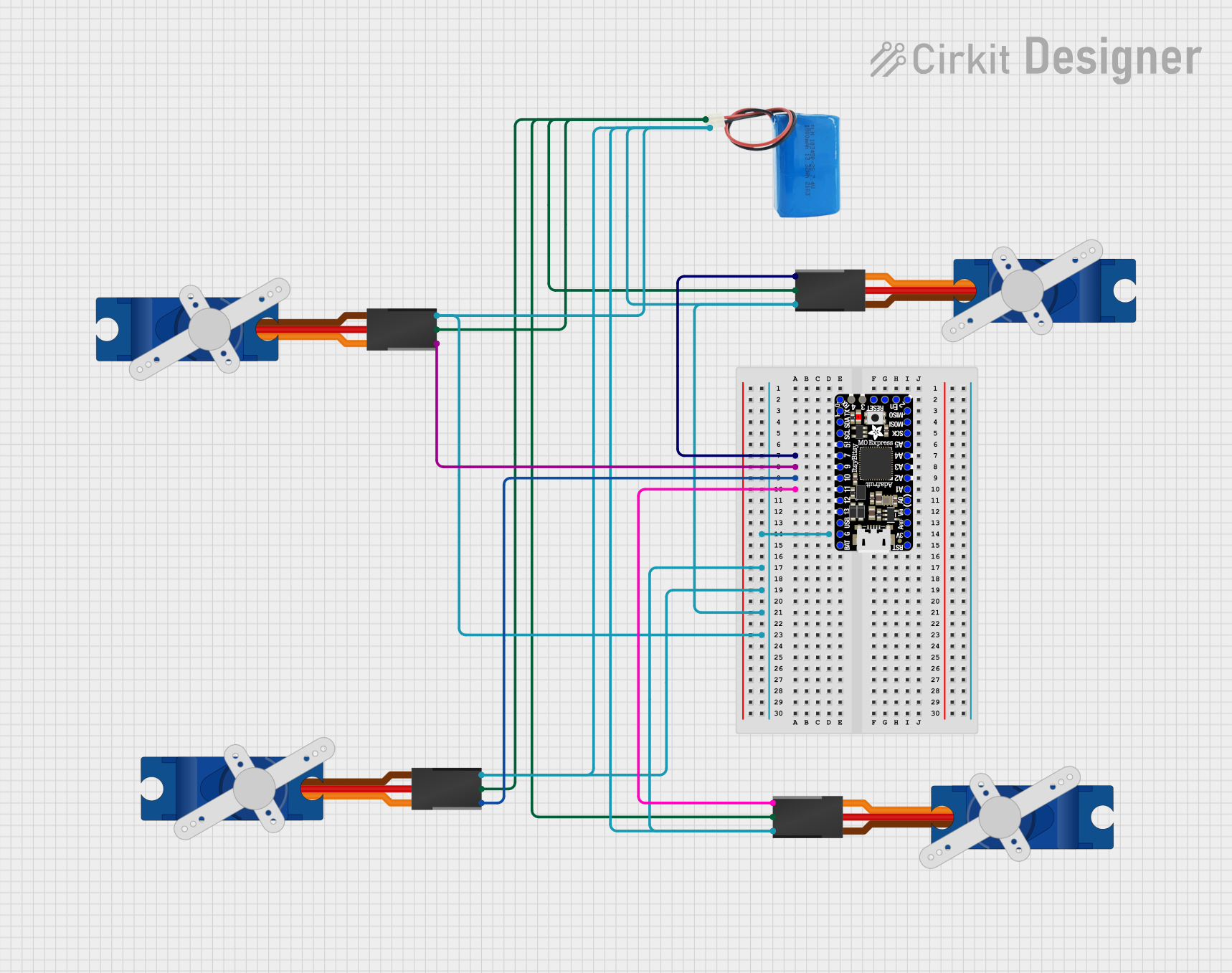
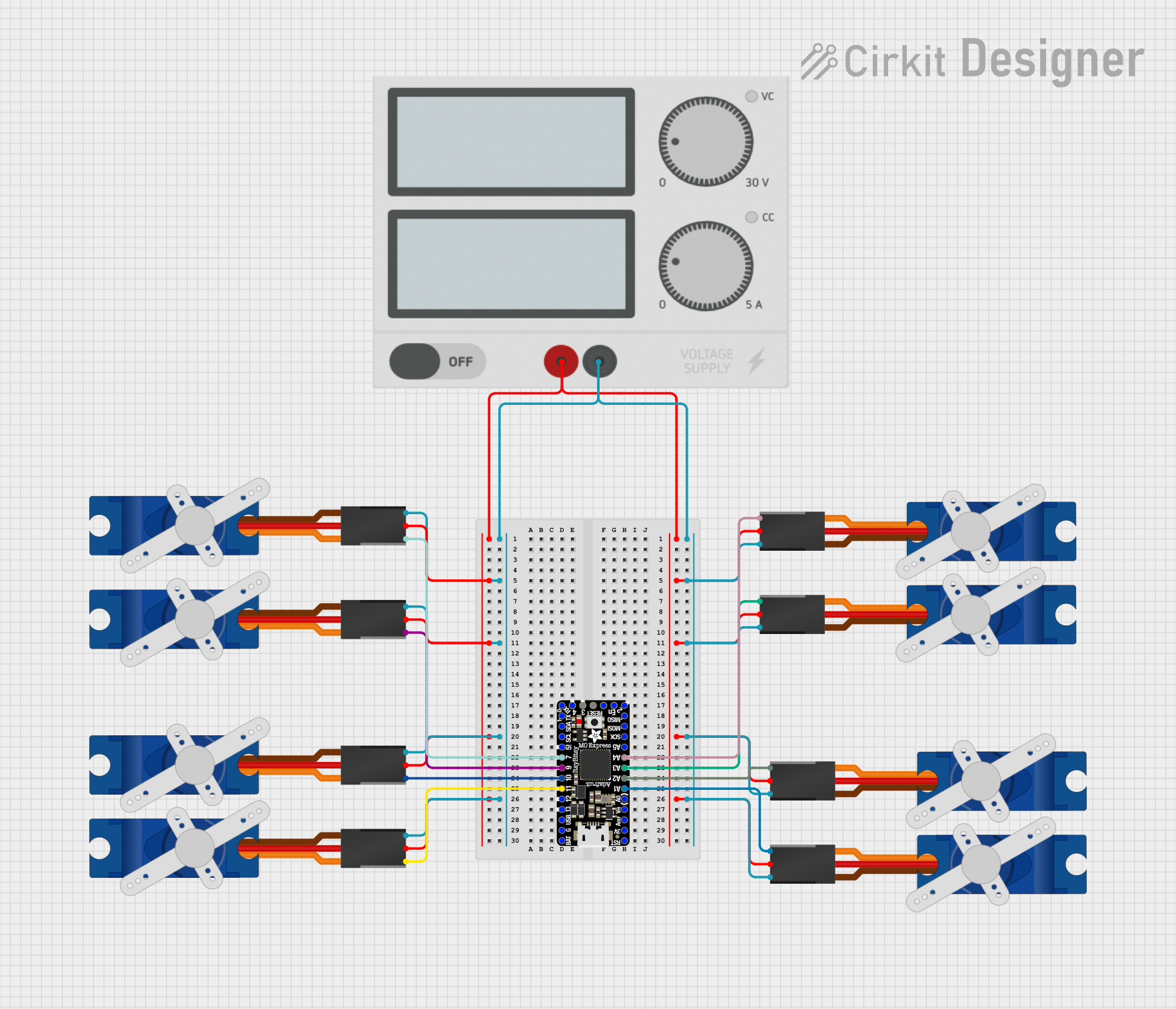

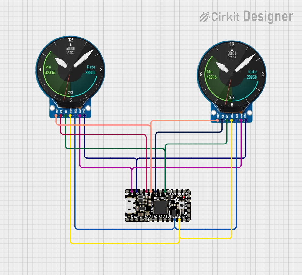
Explore Projects Built with Itsy Bitsy M0 Express
Technical Specifications
Key Technical Details
- Microcontroller: ATSAMD21G18, 32-bit ARM Cortex M0+
- Clock Speed: 48 MHz
- Operating Voltage: 3.3V
- I/O Pin Voltage: 3.3V (not 5V tolerant)
- Digital I/O Pins: 23 (including 12 PWM)
- Analog Inputs: 10 (12-bit ADC channels)
- Analog Outputs: 1 (10-bit DAC)
- Flash Memory: 256 KB
- SRAM: 32 KB
- EEPROM: None (emulated in flash with 16 KB reserved)
- USB: Native in the M0, can act as USB device or host
- Serial Interfaces: I2C, SPI, UART
- PWM Frequency: Up to 48 MHz
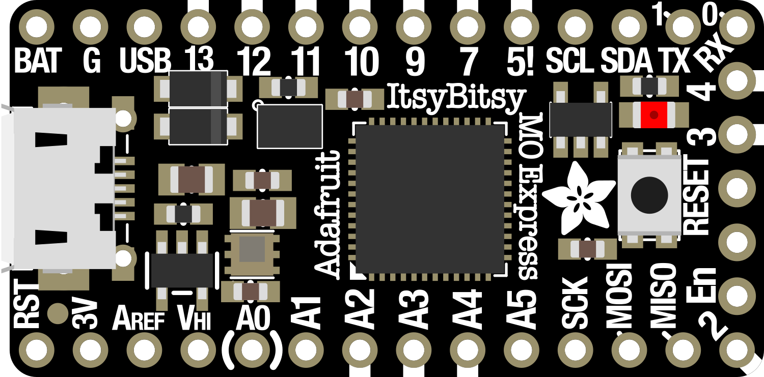
Pin Configuration and Descriptions
| Pin Number | Function | Description |
|---|---|---|
| 1 | GND | Ground |
| 2 | VIN | Voltage input for the board |
| 3-5 | Analog Pins | Analog input pins (A0-A2) |
| 6-8 | Digital Pins | Digital I/O pins (D0-D2) |
| 9 | RESET | Reset pin |
| 10-12 | SPI Interface | SPI communication pins (SCK, MISO, MOSI) |
| 13-15 | I2C Interface | I2C communication pins (SCL, SDA, REF) |
| 16-18 | UART Interface | UART communication pins (RX, TX, ALT) |
| 19-21 | PWM Pins | PWM output pins (PWM0-PWM2) |
| 22 | 3V3 | 3.3V output from the regulator |
| 23 | 5V | 5V output (when USB is connected) |
Note: This is a simplified pinout for illustrative purposes. Refer to the official datasheet for complete pin descriptions.
Usage Instructions
Integrating with a Circuit
To use the Itsy Bitsy M0 Express in a circuit:
- Connect the VIN pin to a 5V power supply if not using USB for power.
- Ensure that all connected components are compatible with 3.3V logic levels.
- Use the digital and analog pins to interface with sensors, actuators, and other peripherals.
- Utilize the SPI, I2C, or UART pins for communication with other microcontrollers or modules.
Programming
The Itsy Bitsy M0 Express can be programmed using the Arduino IDE:
- Install the Arduino IDE and the necessary board package for the Itsy Bitsy M0 Express.
- Select the Itsy Bitsy M0 Express from the board menu.
- Write your sketch and upload it to the board using a micro USB cable.
Best Practices
- Always disconnect the board from power before making or altering connections.
- Avoid applying more than 3.3V to any I/O pin to prevent damage.
- Use a current limiting resistor when driving LEDs or similar components.
Troubleshooting and FAQs
Common Issues
- Board not recognized by the computer: Ensure the micro USB cable is data-capable and the board is properly powered.
- Incorrect voltages at I/O pins: Verify that the board is operating at 3.3V and that the power supply is stable.
- Sketch not running: Check for proper board and port selection in the Arduino IDE, and ensure the bootloader is intact.
Solutions and Tips
- If the board is not recognized, try a different USB port or cable and press the reset button twice quickly to enter bootloader mode.
- Use a multimeter to check voltages and continuity in your circuit.
- For complex issues, refer to the Itsy Bitsy M0 Express forums and community resources.
Example Code for Arduino UNO
Here's a simple example of blinking an LED connected to pin 13 of the Itsy Bitsy M0 Express using the Arduino IDE:
// Define the LED pin
const int ledPin = 13;

// the setup routine runs once when you press reset:
void setup() {
  // initialize the digital pin as an output.
  pinMode(ledPin, OUTPUT);
}

// the loop routine runs over and over again forever:
void loop() {
  digitalWrite(ledPin, HIGH);   // turn the LED on (HIGH is the voltage level)
  delay(1000);                  // wait for a second
  digitalWrite(ledPin, LOW);    // turn the LED off by making the voltage LOW
  delay(1000);                  // wait for a second
}
Note: This code is for demonstration purposes and assumes an LED with an appropriate current-limiting resistor is connected to pin 13.
Remember to keep code comments concise and within the 80 character line length limit.