Cirkit Designer LogoCirkit DesignerYour all-in-one circuit design IDE Launch Cirkit Designer App

How to Use Pixhawk 6C: Examples, Pinouts, and Specs

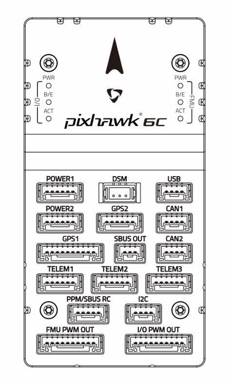
Image of Pixhawk 6CDesign with Pixhawk 6C in Cirkit Designer

Introduction

The Pixhawk 6C is an advanced flight control hardware designed specifically for drones and UAVs. It features a powerful processor, multiple sensor inputs, and compatibility with various autopilot software platforms such as PX4 and ArduPilot. This flight controller is engineered to deliver robust performance for autonomous flight, including GPS navigation, stabilization, and telemetry. Its modular design and extensive connectivity options make it a versatile choice for both hobbyists and professional drone developers.

Explore Projects Built with Pixhawk 6C

Use Cirkit Designer to design, explore, and prototype these projects online. Some projects support real-time simulation. Click "Open Project" to start designing instantly!
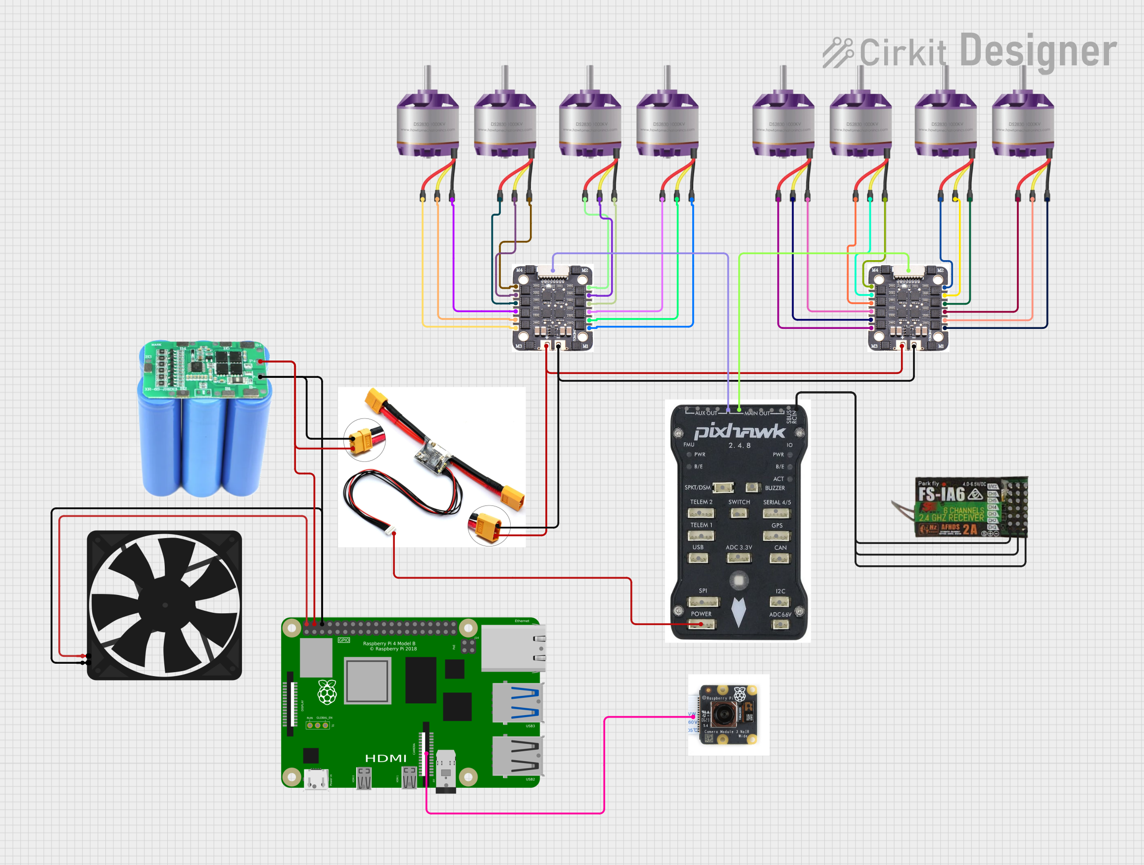
Image of Raspberry Pi-Controlled Drone with Brushless Motors and Camera Module: A project utilizing Pixhawk 6C in a practical application
Raspberry Pi-Controlled Drone with Brushless Motors and Camera Module

This circuit is designed for a multi-motor application, likely a drone or a similar vehicle, featuring eight brushless motors controlled by two 4-in-1 electronic speed controllers (ESCs). The ESCs are powered by a 3s2p 18650 battery pack and interfaced with a Pixhawk flight controller for motor management. Additionally, the system includes a Raspberry Pi 4B for advanced processing and control, which is connected to a NoIR camera module and a cooling fan, and a power module to supply and monitor the power to the Pixhawk.

Open Project in Cirkit Designer
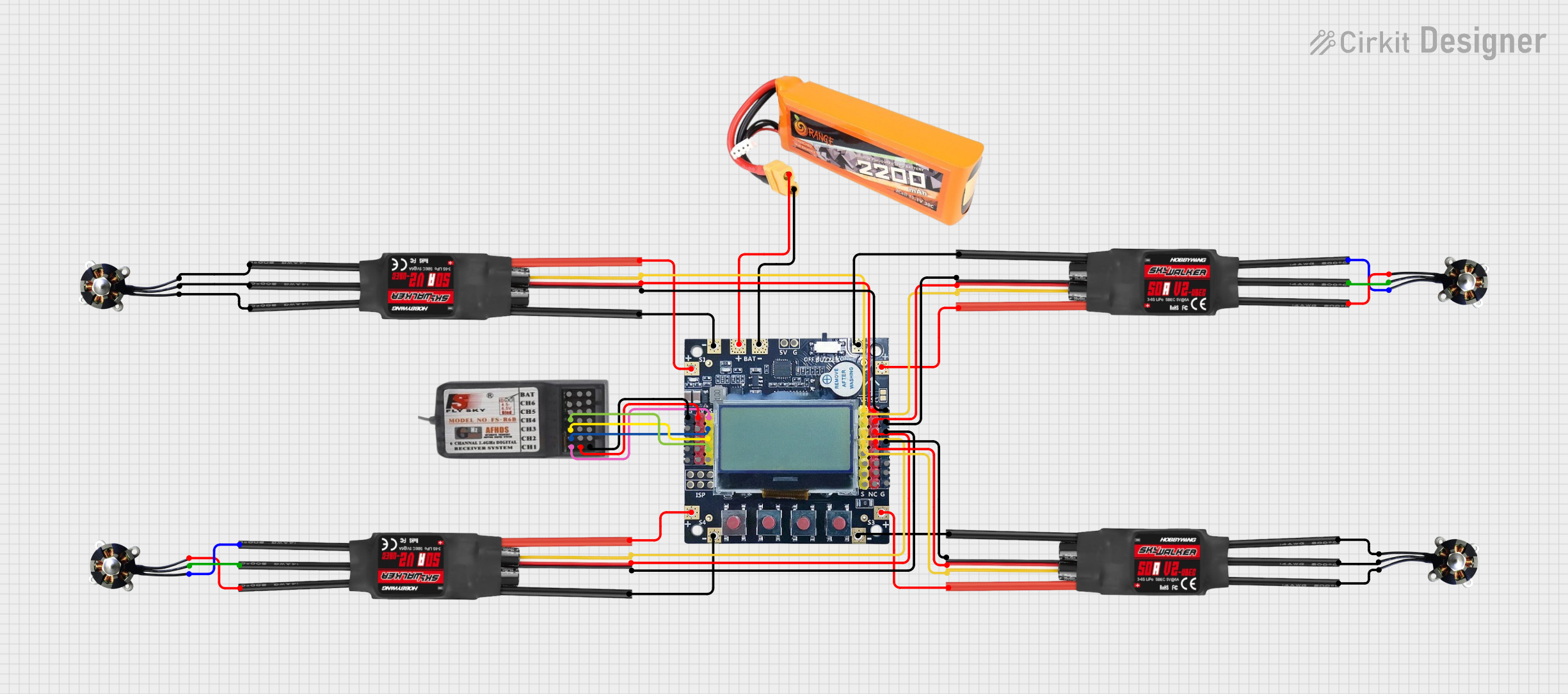
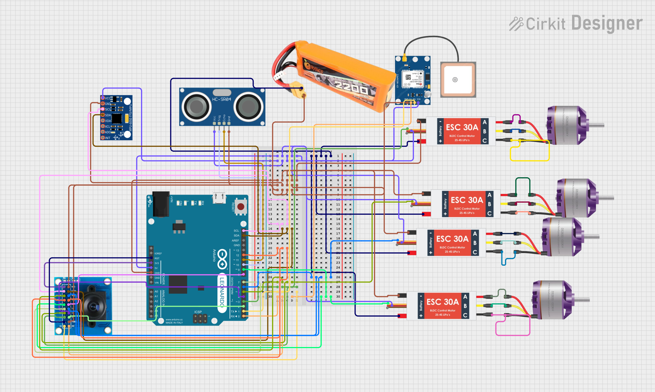
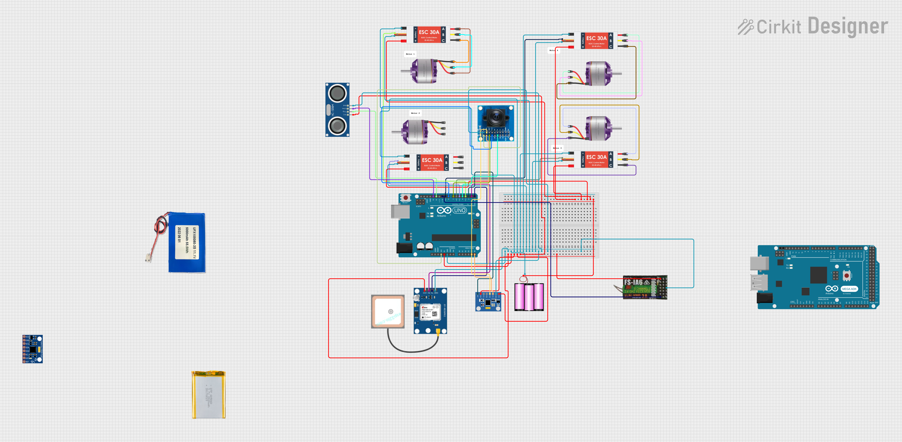
Image of Quadcopter Flight Controller with GPS and Ultrasonic Sensor: A project utilizing Pixhawk 6C in a practical application
Quadcopter Flight Controller with GPS and Ultrasonic Sensor

This circuit is designed for a multirotor UAV, featuring an Arduino Leonardo that controls four brushless motors via ESCs, processes data from an MPU-6050 for stabilization, reads from a GPS module for navigation, and utilizes an ultrasonic sensor for altitude control. Additionally, it includes a camera module for imaging purposes, with all components powered by a single LiPo battery.

Open Project in Cirkit Designer
Image of Arduino UNO Based Quadcopter Control System with GPS, MPU6050, and Ultrasonic Sensor: A project utilizing Pixhawk 6C in a practical application
Arduino UNO Based Quadcopter Control System with GPS, MPU6050, and Ultrasonic Sensor

This circuit features an Arduino UNO microcontroller interfaced with a NEO-6M GPS module, an MPU6050 accelerometer/gyroscope, an HC-SR04 ultrasonic sensor, an OV7725 camera module, and a FLYSKY FS-IA6 receiver. It controls four brushless motors through electronic speed controllers (ESCs), which are powered by a 12V battery. The ESCs receive control signals from the Arduino, which likely processes input from the sensors and receiver to adjust the motor speeds, suggesting this could be part of a drone or a similar remotely controlled vehicle.

Open Project in Cirkit Designer

Common Applications and Use Cases

Technical Specifications

Key Technical Details

Specification Value
Processor STM32H743, 32-bit ARM® Cortex®-M7
IMUs (Inertial Measurement Units) 2x ICM-42688-P (accelerometer/gyroscope)
Barometer MS5611
Input Voltage Range 4.3V to 5.4V
Maximum Current 2.5A
GPS Support Dual GPS with RTK support
Communication Interfaces UART, I2C, CAN, SPI, USB, PWM
Dimensions 38.5mm x 55.5mm x 15.5mm
Weight 15g
Operating Temperature Range -20°C to 60°C

Pin Configuration and Descriptions

The Pixhawk 6C features multiple connectors for peripherals and sensors. Below is a summary of the key pin configurations:

Power and Communication Ports

Port Name Pin Description
POWER1/POWER2 Power input for the flight controller
USB-C USB interface for firmware updates and debugging
TELEM1/TELEM2 Telemetry ports for communication with ground stations
GPS1/GPS2 GPS module connections
CAN1/CAN2 CAN bus for peripherals like LiDAR or cameras
I2C I2C bus for external sensors

PWM and Motor Outputs

Port Name Pin Description
MAIN1-MAIN8 PWM outputs for motors or servos
AUX1-AUX6 Auxiliary PWM outputs

Sensor Inputs

Port Name Pin Description
ADC1/ADC2 Analog-to-digital converter inputs
RCIN Input for RC receiver
SPI SPI interface for external sensors

Usage Instructions

How to Use the Pixhawk 6C in a Circuit

  1. Powering the Pixhawk 6C: Connect a compatible power module to the POWER1 or POWER2 port. Ensure the input voltage is within the range of 4.3V to 5.4V.
  2. Connecting Peripherals: Attach sensors, GPS modules, telemetry radios, and other peripherals to their respective ports (e.g., GPS1, TELEM1, I2C).
  3. Motor and Servo Connections: Connect ESCs or servos to the MAIN1-MAIN8 or AUX1-AUX6 ports, depending on your configuration.
  4. Firmware Setup: Use a USB-C cable to connect the Pixhawk 6C to your computer. Install and configure the desired autopilot software (e.g., PX4 or ArduPilot) using a ground control station like QGroundControl or Mission Planner.
  5. Calibrating Sensors: Follow the autopilot software's instructions to calibrate the accelerometer, gyroscope, compass, and other sensors.
  6. Testing: Perform a pre-flight check to ensure all components are functioning correctly.

Important Considerations and Best Practices

Example Code for Arduino UNO Integration

While the Pixhawk 6C is not directly programmable via Arduino, it can communicate with an Arduino UNO using telemetry or I2C. Below is an example of how to read data from the Pixhawk 6C via I2C:

#include <Wire.h>

#define PIXHAWK_I2C_ADDRESS 0x42  // Replace with the actual I2C address of the Pixhawk

void setup() {
  Wire.begin();  // Initialize I2C communication
  Serial.begin(9600);  // Initialize serial communication for debugging
}

void loop() {
  Wire.beginTransmission(PIXHAWK_I2C_ADDRESS);  // Start communication with Pixhawk
  Wire.write(0x00);  // Request data (register address may vary)
  Wire.endTransmission();

  Wire.requestFrom(PIXHAWK_I2C_ADDRESS, 6);  // Request 6 bytes of data
  if (Wire.available() == 6) {
    int16_t data1 = Wire.read() << 8 | Wire.read();  // Read first 2 bytes
    int16_t data2 = Wire.read() << 8 | Wire.read();  // Read next 2 bytes
    int16_t data3 = Wire.read() << 8 | Wire.read();  // Read last 2 bytes

    // Print the received data
    Serial.print("Data1: ");
    Serial.print(data1);
    Serial.print(", Data2: ");
    Serial.print(data2);
    Serial.print(", Data3: ");
    Serial.println(data3);
  }

  delay(100);  // Wait before the next request
}

Troubleshooting and FAQs

Common Issues and Solutions

  1. Issue: The Pixhawk 6C does not power on.

    • Solution: Check the power module connection and ensure the input voltage is within the specified range (4.3V to 5.4V). Verify that the power module is functioning correctly.
  2. Issue: GPS module is not detected.

    • Solution: Ensure the GPS module is connected to the correct port (GPS1 or GPS2). Verify the wiring and check for loose connections. Confirm that the GPS module is compatible with the Pixhawk 6C.
  3. Issue: Motors are not responding.

    • Solution: Verify that the ESCs are connected to the correct PWM outputs (MAIN1-MAIN8). Check the motor configuration in the autopilot software and ensure the ESCs are calibrated.
  4. Issue: Telemetry data is not being received.

    • Solution: Confirm that the telemetry radio is connected to the correct port (TELEM1 or TELEM2). Check the baud rate settings in the autopilot software and ensure they match the telemetry radio's configuration.

FAQs