How to Use Max30205: Examples, Pinouts, and Specs
Introduction
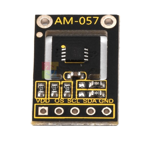
The MAX30205, manufactured by AM057, is a high-accuracy digital temperature sensor designed to provide precise temperature readings with a resolution of 0.0625°C. It operates over an I2C interface, making it easy to integrate into a wide range of applications. The sensor is optimized for low power consumption, making it ideal for battery-powered devices and wearable electronics.
Explore Projects Built with Max30205

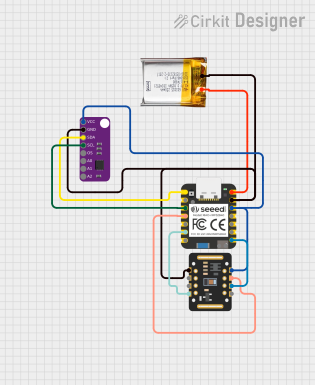


Explore Projects Built with Max30205
Common Applications and Use Cases
- Medical devices (e.g., body temperature monitoring)
- Wearable health and fitness trackers
- Industrial temperature monitoring
- Environmental sensing in IoT devices
- Consumer electronics requiring precise temperature control
Technical Specifications
The MAX30205 is designed to deliver high performance and reliability. Below are its key technical details:
Key Technical Details
| Parameter | Value |
|---|---|
| Supply Voltage (VDD) | 2.7V to 3.3V |
| Temperature Range | 0°C to +50°C |
| Temperature Accuracy | ±0.1°C (human body temperature) |
| Resolution | 0.0625°C |
| Communication Interface | I2C |
| Power Consumption | 600 µA (typical) |
| Shutdown Current | 0.1 µA (typical) |
| Package Type | 8-pin TDFN |
Pin Configuration and Descriptions
The MAX30205 is available in an 8-pin TDFN package. Below is the pinout and description:
| Pin Number | Pin Name | Description |
|---|---|---|
| 1 | SDA | Serial Data Line for I2C communication |
| 2 | SCL | Serial Clock Line for I2C communication |
| 3 | ALERT | Over-temperature alert output (open-drain) |
| 4 | GND | Ground |
| 5 | VDD | Power supply input (2.7V to 3.3V) |
| 6 | NC | No connection (leave unconnected) |
| 7 | NC | No connection (leave unconnected) |
| 8 | NC | No connection (leave unconnected) |
Usage Instructions
The MAX30205 is straightforward to use in a circuit, thanks to its I2C interface. Below are the steps and considerations for integrating the sensor:
How to Use the MAX30205 in a Circuit
- Power Supply: Connect the VDD pin to a 2.7V to 3.3V power source and the GND pin to ground.
- I2C Communication: Connect the SDA and SCL pins to the corresponding I2C lines of your microcontroller. Use pull-up resistors (typically 4.7kΩ) on both lines.
- Alert Pin (Optional): The ALERT pin can be used to trigger an interrupt when the temperature exceeds a user-defined threshold. If unused, leave it unconnected.
- No-Connection Pins: Leave the NC pins unconnected.
Important Considerations and Best Practices
- Bypass Capacitor: Place a 0.1µF ceramic capacitor close to the VDD pin to stabilize the power supply.
- I2C Address: The MAX30205 has a fixed I2C address of
0x48. Ensure no other devices on the I2C bus share this address. - Temperature Range: Operate the sensor within its specified temperature range (0°C to +50°C) for accurate readings.
- Low Power Mode: Use the shutdown mode to minimize power consumption when the sensor is not in use.
Example Code for Arduino UNO
Below is an example of how to interface the MAX30205 with an Arduino UNO to read temperature data:
#include <Wire.h>

// MAX30205 I2C address
#define MAX30205_ADDRESS 0x48

void setup() {
  Wire.begin(); // Initialize I2C communication
  Serial.begin(9600); // Initialize serial communication for debugging
}

void loop() {
  float temperature = readTemperature();
  Serial.print("Temperature: ");
  Serial.print(temperature);
  Serial.println(" °C");
  delay(1000); // Wait 1 second before the next reading
}

float readTemperature() {
  Wire.beginTransmission(MAX30205_ADDRESS); // Start communication with MAX30205
  Wire.write(0x00); // Point to the temperature register
  Wire.endTransmission(false); // Send the address and keep the connection active

  Wire.requestFrom(MAX30205_ADDRESS, 2); // Request 2 bytes of temperature data
  if (Wire.available() == 2) {
    uint8_t msb = Wire.read(); // Read the most significant byte
    uint8_t lsb = Wire.read(); // Read the least significant byte
    int16_t rawTemperature = (msb << 8) | lsb; // Combine the two bytes
    return rawTemperature * 0.00390625; // Convert to Celsius (0.0625°C per LSB)
  } else {
    return NAN; // Return NaN if data is not available
  }
}
Troubleshooting and FAQs
Common Issues and Solutions
No Temperature Reading:
- Cause: Incorrect I2C wiring or address conflict.
- Solution: Verify the SDA and SCL connections. Ensure no other devices on the I2C bus use the same address (
0x48).
Inaccurate Temperature Readings:
- Cause: Operating outside the specified temperature range or insufficient power supply.
- Solution: Ensure the sensor operates within 0°C to +50°C and the VDD is stable at 2.7V to 3.3V.
ALERT Pin Not Triggering:
- Cause: Incorrect configuration of the over-temperature threshold.
- Solution: Configure the threshold registers correctly via I2C commands.
High Power Consumption:
- Cause: Sensor not in shutdown mode when idle.
- Solution: Use the shutdown mode to reduce power consumption when the sensor is not actively measuring.
FAQs
Q: Can the MAX30205 measure temperatures below 0°C or above 50°C?
A: No, the MAX30205 is designed for a temperature range of 0°C to +50°C. Operating outside this range may result in inaccurate readings or damage to the sensor.
Q: What is the resolution of the temperature readings?
A: The MAX30205 provides temperature readings with a resolution of 0.0625°C.
Q: Is the MAX30205 suitable for battery-powered devices?
A: Yes, the sensor's low power consumption (600 µA typical) and shutdown mode (0.1 µA typical) make it ideal for battery-operated applications.