Cirkit Designer Logo
Cirkit Designer
Your all-in-one circuit design IDE
Home / 
Component Documentation

How to Use D24V90F5: Examples, Pinouts, and Specs
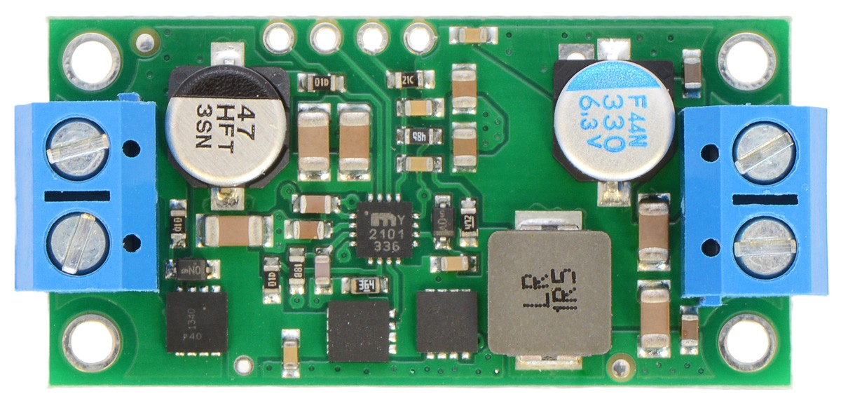

Image of D24V90F5
Cirkit Designer LogoDesign with D24V90F5 in Cirkit Designer

Introduction

The D24V90F5 is a high-performance DC-DC step-down voltage regulator capable of delivering a stable 5V output from a wide input voltage range of 6V to 36V. With a maximum output power of 90W, this regulator is designed for applications requiring high efficiency and reliability. Its compact design and robust features make it suitable for powering microcontrollers, sensors, communication devices, and other electronic systems.

Explore Projects Built with D24V90F5
Use Cirkit Designer to design, explore, and prototype these projects online. Some projects support real-time simulation. Click "Open Project" to start designing instantly!
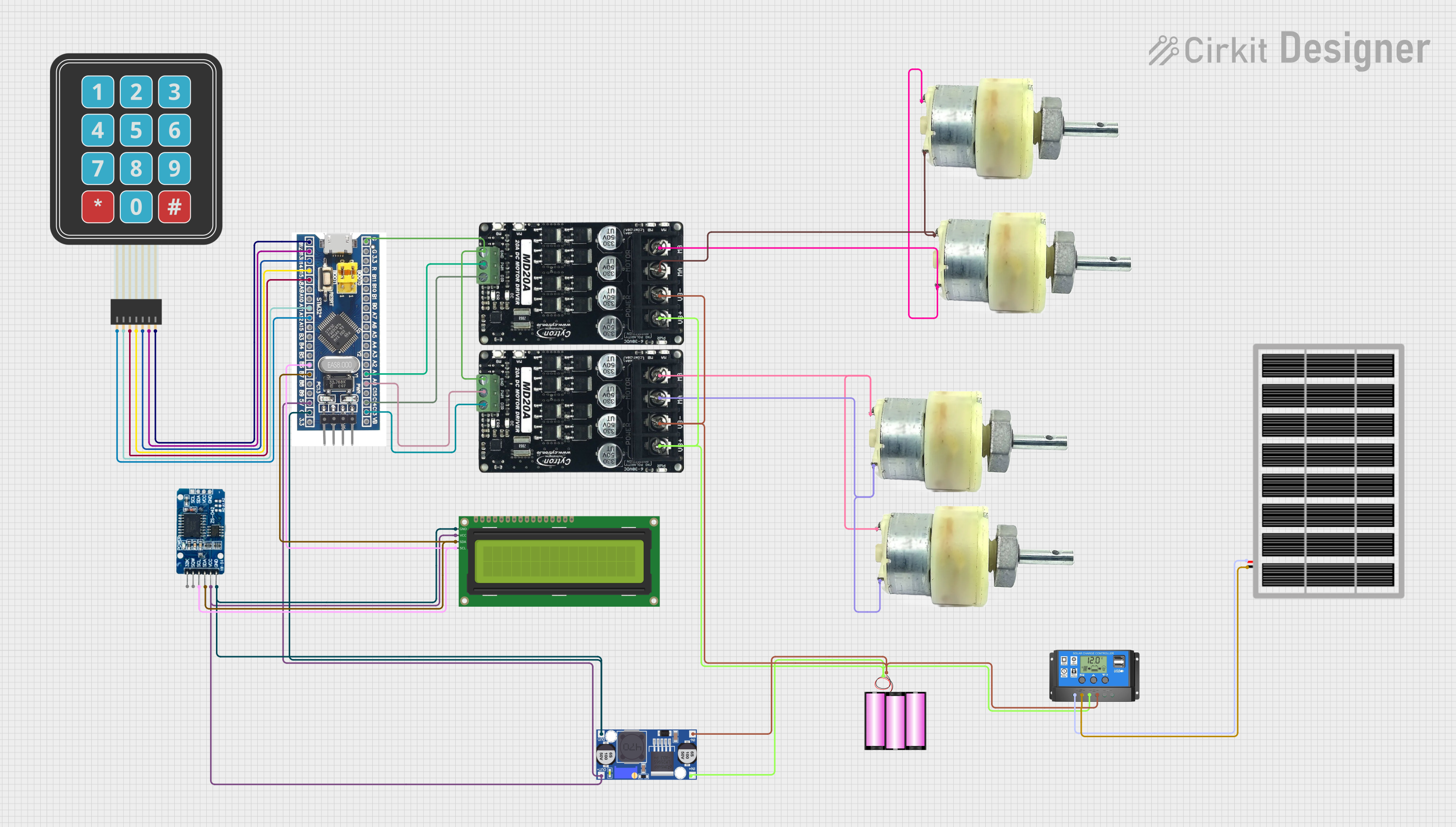
Solar-Powered STM32-Based Automation System with Matrix Keypad and RTC
Image of soloar cleaner : A project utilizing D24V90F5 in a practical application
This circuit features an STM32F103C8T6 microcontroller interfaced with a membrane matrix keypad for input, an RTC DS3231 for real-time clock functionality, and a 16x2 I2C LCD for display. It controls four 12V geared motors through two MD20 CYTRON motor drivers, with the motor power supplied by a 12V battery regulated by a buck converter. The battery is charged via a solar panel connected through a solar charge controller, ensuring a renewable energy source for the system.
Cirkit Designer LogoOpen Project in Cirkit Designer
ESP32-Powered Wi-Fi Controlled Robotic Car with OLED Display and Ultrasonic Sensor
Image of playbot: A project utilizing D24V90F5 in a practical application
This circuit is a battery-powered system featuring an ESP32 microcontroller that controls an OLED display, a motor driver for two hobby motors, an ultrasonic sensor for distance measurement, and a DFPlayer Mini for audio output through a loudspeaker. The TP4056 module manages battery charging, and a step-up boost converter provides a stable 5V supply to the components.
Cirkit Designer LogoOpen Project in Cirkit Designer
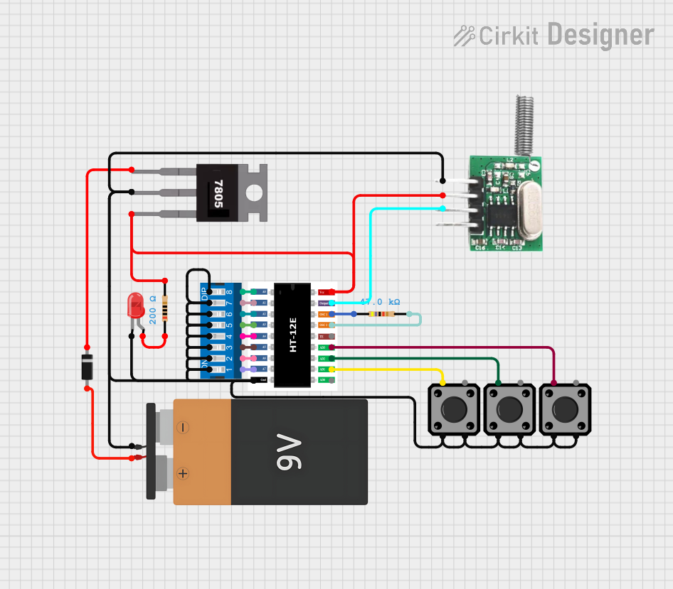
Configurable Battery-Powered RF Signal Transmitter with DIP Switch Settings
Image of fyp transmitter: A project utilizing D24V90F5 in a practical application
This circuit appears to be a configurable encoder system with an RF transmission capability. The encoder's address pins (A0-A7) are connected to a DIP switch for setting the address, and its data output (DO) is connected to an RF transmitter, allowing the encoded signal to be wirelessly transmitted. The circuit is powered by a 9V battery, regulated to 5V by a 7805 voltage regulator, and includes a diode for polarity protection. Tactile switches are connected to the encoder's data inputs (D1-D3), and an LED with a current-limiting resistor indicates power or activity.
Cirkit Designer LogoOpen Project in Cirkit Designer
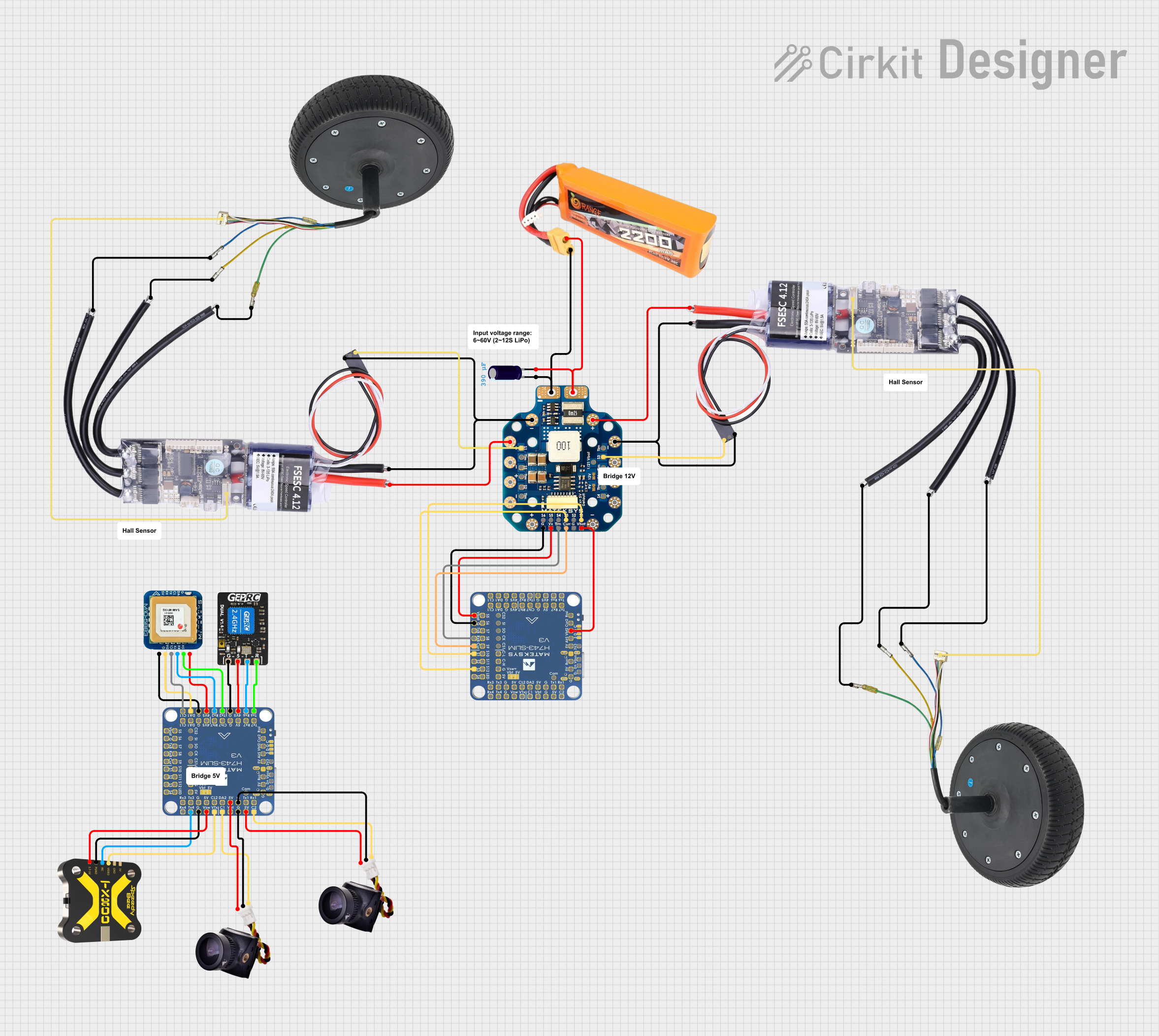
Battery-Powered FPV Drone with Telemetry and Dual Motor Control
Image of Krul': A project utilizing D24V90F5 in a practical application
This circuit appears to be a power distribution and control system for a vehicle with two motorized wheels, possibly a drone or a robot. It includes a lipo battery connected to a Power Distribution Board (PDB) that distributes power to two Electronic Speed Controllers (ESCs) which in turn control the speed and direction of the motors. The system also integrates a flight controller (H743-SLIM V3) for managing various peripherals including GPS, FPV camera system, and a telemetry link (ExpressLRS).
Cirkit Designer LogoOpen Project in Cirkit Designer

Explore Projects Built with D24V90F5

Use Cirkit Designer to design, explore, and prototype these projects online. Some projects support real-time simulation. Click "Open Project" to start designing instantly!
Image of soloar cleaner : A project utilizing D24V90F5 in a practical application
Solar-Powered STM32-Based Automation System with Matrix Keypad and RTC
This circuit features an STM32F103C8T6 microcontroller interfaced with a membrane matrix keypad for input, an RTC DS3231 for real-time clock functionality, and a 16x2 I2C LCD for display. It controls four 12V geared motors through two MD20 CYTRON motor drivers, with the motor power supplied by a 12V battery regulated by a buck converter. The battery is charged via a solar panel connected through a solar charge controller, ensuring a renewable energy source for the system.
Cirkit Designer LogoOpen Project in Cirkit Designer
Image of playbot: A project utilizing D24V90F5 in a practical application
ESP32-Powered Wi-Fi Controlled Robotic Car with OLED Display and Ultrasonic Sensor
This circuit is a battery-powered system featuring an ESP32 microcontroller that controls an OLED display, a motor driver for two hobby motors, an ultrasonic sensor for distance measurement, and a DFPlayer Mini for audio output through a loudspeaker. The TP4056 module manages battery charging, and a step-up boost converter provides a stable 5V supply to the components.
Cirkit Designer LogoOpen Project in Cirkit Designer
Image of fyp transmitter: A project utilizing D24V90F5 in a practical application
Configurable Battery-Powered RF Signal Transmitter with DIP Switch Settings
This circuit appears to be a configurable encoder system with an RF transmission capability. The encoder's address pins (A0-A7) are connected to a DIP switch for setting the address, and its data output (DO) is connected to an RF transmitter, allowing the encoded signal to be wirelessly transmitted. The circuit is powered by a 9V battery, regulated to 5V by a 7805 voltage regulator, and includes a diode for polarity protection. Tactile switches are connected to the encoder's data inputs (D1-D3), and an LED with a current-limiting resistor indicates power or activity.
Cirkit Designer LogoOpen Project in Cirkit Designer
Image of Krul': A project utilizing D24V90F5 in a practical application
Battery-Powered FPV Drone with Telemetry and Dual Motor Control
This circuit appears to be a power distribution and control system for a vehicle with two motorized wheels, possibly a drone or a robot. It includes a lipo battery connected to a Power Distribution Board (PDB) that distributes power to two Electronic Speed Controllers (ESCs) which in turn control the speed and direction of the motors. The system also integrates a flight controller (H743-SLIM V3) for managing various peripherals including GPS, FPV camera system, and a telemetry link (ExpressLRS).
Cirkit Designer LogoOpen Project in Cirkit Designer

Common Applications

  • Powering microcontrollers (e.g., Arduino, Raspberry Pi)
  • Robotics and automation systems
  • Battery-powered devices
  • Industrial control systems
  • Portable electronics

Technical Specifications

Key Specifications

Parameter Value
Input Voltage Range 6V to 36V
Output Voltage 5V
Maximum Output Current 18A
Maximum Output Power 90W
Efficiency Up to 95%
Operating Temperature -40°C to +85°C
Dimensions 1.9" × 1.0" × 0.4" (approx.)

Pin Configuration and Descriptions

Pin Name Pin Type Description
VIN Input Connect to the positive terminal of the input voltage source.
GND Ground Connect to the ground of the input voltage source.
VOUT Output Provides the regulated 5V output.
ENABLE Control Logic input to enable or disable the regulator. High = Enabled, Low = Disabled.

Usage Instructions

How to Use the D24V90F5 in a Circuit

  1. Connect the Input Voltage:

    • Connect the VIN pin to a DC voltage source within the range of 6V to 36V.
    • Ensure the input voltage is stable and within the specified range to avoid damage.
  2. Connect the Ground:

    • Connect the GND pin to the ground of the input voltage source and the load.
  3. Connect the Output:

    • Connect the VOUT pin to the load requiring a 5V supply.
    • Ensure the load does not exceed the maximum output current of 18A.
  4. Enable the Regulator:

    • To enable the regulator, apply a high logic level (e.g., 3.3V or 5V) to the ENABLE pin.
    • To disable the regulator, apply a low logic level or leave the ENABLE pin unconnected.
  5. Add Capacitors (Optional):

    • For improved stability, you can add input and output capacitors close to the regulator. Use low-ESR capacitors with values recommended in the datasheet.

Important Considerations

  • Heat Dissipation: At high currents, the regulator may generate heat. Use a heatsink or ensure proper ventilation to maintain safe operating temperatures.
  • Input Voltage Range: Do not exceed the maximum input voltage of 36V to prevent damage to the regulator.
  • Load Requirements: Ensure the connected load does not draw more than 18A to avoid overloading the regulator.

Example: Using the D24V90F5 with an Arduino UNO

The D24V90F5 can be used to power an Arduino UNO by providing a stable 5V supply. Below is an example circuit and Arduino code to demonstrate its usage.

Circuit Connections

  • Connect the VIN pin of the D24V90F5 to a 12V DC power source.
  • Connect the GND pin to the ground of the power source and the Arduino UNO.
  • Connect the VOUT pin to the 5V pin of the Arduino UNO.

Arduino Code Example

// Example code to blink an LED connected to pin 13 of the Arduino UNO
// Ensure the D24V90F5 is providing a stable 5V supply to the Arduino

void setup() {
  pinMode(13, OUTPUT); // Set pin 13 as an output
}

void loop() {
  digitalWrite(13, HIGH); // Turn the LED on
  delay(1000);            // Wait for 1 second
  digitalWrite(13, LOW);  // Turn the LED off
  delay(1000);            // Wait for 1 second
}

Troubleshooting and FAQs

Common Issues and Solutions

  1. No Output Voltage:

    • Check if the ENABLE pin is connected to a high logic level.
    • Verify the input voltage is within the specified range (6V to 36V).
    • Ensure proper connections to the VIN, GND, and VOUT pins.
  2. Overheating:

    • Ensure the load does not exceed the maximum output current of 18A.
    • Use a heatsink or improve ventilation to dissipate heat.
  3. Output Voltage Fluctuations:

    • Add low-ESR capacitors to the input and output for improved stability.
    • Check for loose or poor connections in the circuit.
  4. Regulator Not Enabling:

    • Verify the ENABLE pin is receiving a high logic level.
    • Check for any shorts or incorrect wiring.

FAQs

Q: Can the D24V90F5 be used with a 24V input?
A: Yes, the D24V90F5 supports input voltages up to 36V, so 24V is within the acceptable range.

Q: What happens if the input voltage exceeds 36V?
A: Exceeding the maximum input voltage can damage the regulator. Always ensure the input voltage stays within the specified range.

Q: Is the D24V90F5 suitable for battery-powered applications?
A: Yes, its high efficiency and wide input voltage range make it ideal for battery-powered systems.

Q: Can I leave the ENABLE pin unconnected?
A: Yes, leaving the ENABLE pin unconnected will disable the regulator. To enable it, connect the pin to a high logic level.

This concludes the documentation for the D24V90F5. For further assistance, refer to the manufacturer's datasheet or contact technical support.