Cirkit Designer Logo
Cirkit Designer
Your all-in-one circuit design IDE
Home / 
Component Documentation

How to Use SparkFun gator:microphone - micro:bit Accessory Board: Examples, Pinouts, and Specs

Image of SparkFun gator:microphone - micro:bit Accessory Board
Cirkit Designer LogoDesign with SparkFun gator:microphone - micro:bit Accessory Board in Cirkit Designer

Introduction

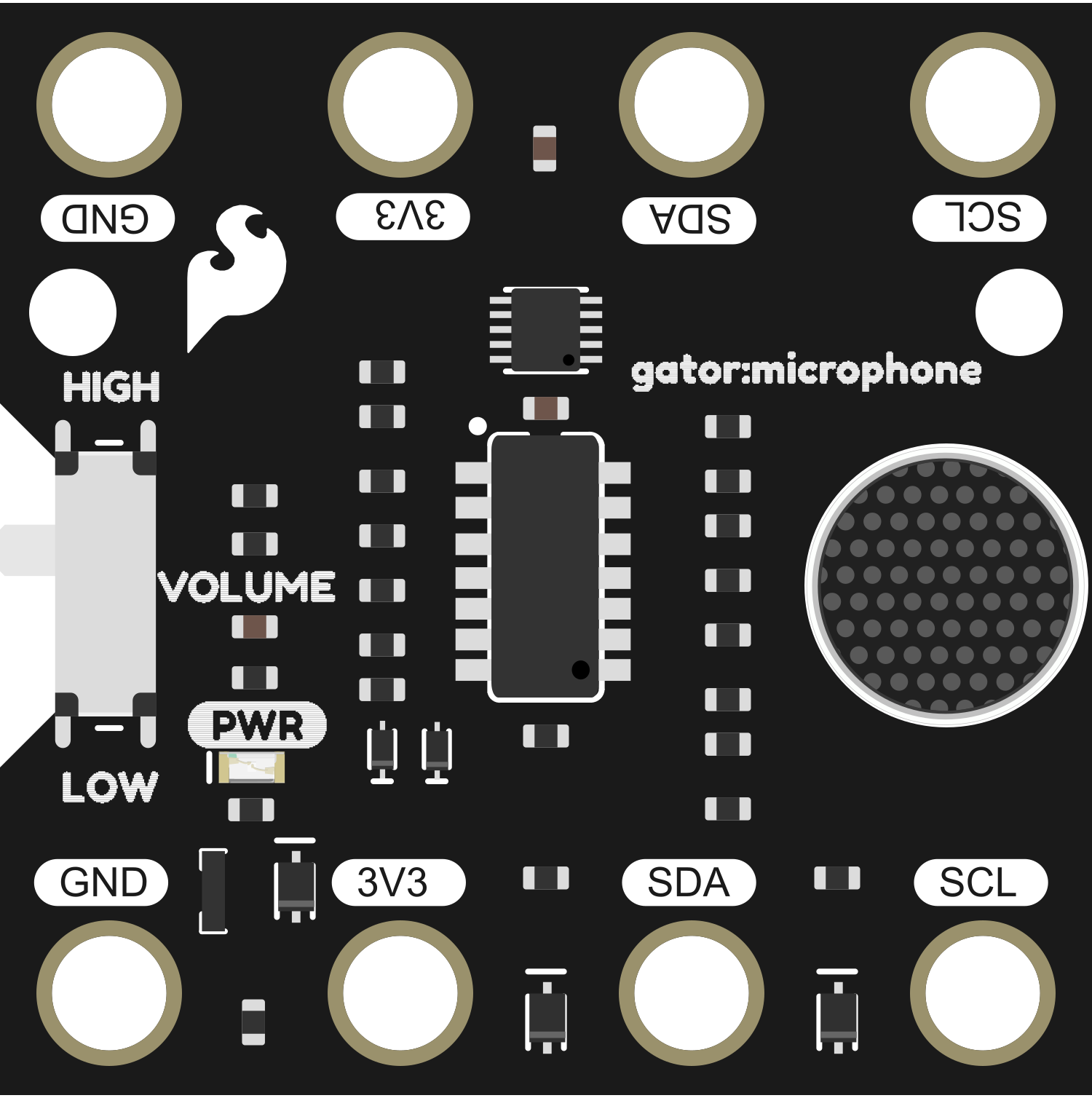
The SparkFun gator:microphone is an innovative accessory board specifically designed for the micro:bit platform. This compact module is capable of detecting and analyzing sound and audio signals, making it an ideal choice for educational projects, interactive installations, and hobbyist experiments involving audio input.

Explore Projects Built with SparkFun gator:microphone - micro:bit Accessory Board

Use Cirkit Designer to design, explore, and prototype these projects online. Some projects support real-time simulation. Click "Open Project" to start designing instantly!
ESP32-Based Voice Assistant with Battery-Powered Microphone and Speaker
Image of Minor: A project utilizing SparkFun gator:microphone - micro:bit Accessory Board in a practical application
This circuit is a voice-controlled system that uses an ESP32 microcontroller to process audio input from a microphone, send the data to a Gemini API for speech-to-text conversion, and output responses through a speaker. It includes an IR sensor for additional input, an LED for status indication, and a battery with a charging module for power management.
Cirkit Designer LogoOpen Project in Cirkit Designer
ESP32-Based Voice-Controlled Speaker
Image of Main Design: A project utilizing SparkFun gator:microphone - micro:bit Accessory Board in a practical application
This circuit is a digital voice playback and recording system powered by a 3.7V battery. It features an ESP32 microcontroller for processing, an Adafruit MAX98357A amplifier to drive a loudspeaker for audio output, and an Adafruit MAX9814 microphone amplifier for audio input. A pushbutton provides user interaction, and a 3.3V regulator ensures stable power supply to the components.
Cirkit Designer LogoOpen Project in Cirkit Designer
Dual-Microcontroller Audio Processing System with Visual Indicators and Battery Management
Image of proto thesis 2: A project utilizing SparkFun gator:microphone - micro:bit Accessory Board in a practical application
This is a portable audio-visual device featuring two Wemos microcontrollers for processing, Adafruit MAX4466 microphone amplifiers for audio input, and an LCD TFT screen for display. It includes power management with TP4056 modules and LiPo batteries, and user-controlled toggle and rocker switches.
Cirkit Designer LogoOpen Project in Cirkit Designer
ESP32-Based Audio Player with GPS and SD Card Storage
Image of Kidventure: A project utilizing SparkFun gator:microphone - micro:bit Accessory Board in a practical application
This circuit features an ESP32 microcontroller connected to a GPS NEO 6M module, an INMP441 microphone, a Max98357 audio amplifier, a MicroSD card breakout board, and a loudspeaker. The ESP32 is configured to communicate with the GPS module via serial connection, record audio through the microphone using I2S, play audio via the amplifier, and read/write data to the MicroSD card. The embedded code on the ESP32 is set up to use Google TTS (Text-To-Speech) to generate speech that is output through the loudspeaker.
Cirkit Designer LogoOpen Project in Cirkit Designer

Explore Projects Built with SparkFun gator:microphone - micro:bit Accessory Board

Use Cirkit Designer to design, explore, and prototype these projects online. Some projects support real-time simulation. Click "Open Project" to start designing instantly!
Image of Minor: A project utilizing SparkFun gator:microphone - micro:bit Accessory Board in a practical application
ESP32-Based Voice Assistant with Battery-Powered Microphone and Speaker
This circuit is a voice-controlled system that uses an ESP32 microcontroller to process audio input from a microphone, send the data to a Gemini API for speech-to-text conversion, and output responses through a speaker. It includes an IR sensor for additional input, an LED for status indication, and a battery with a charging module for power management.
Cirkit Designer LogoOpen Project in Cirkit Designer
Image of Main Design: A project utilizing SparkFun gator:microphone - micro:bit Accessory Board in a practical application
ESP32-Based Voice-Controlled Speaker
This circuit is a digital voice playback and recording system powered by a 3.7V battery. It features an ESP32 microcontroller for processing, an Adafruit MAX98357A amplifier to drive a loudspeaker for audio output, and an Adafruit MAX9814 microphone amplifier for audio input. A pushbutton provides user interaction, and a 3.3V regulator ensures stable power supply to the components.
Cirkit Designer LogoOpen Project in Cirkit Designer
Image of proto thesis 2: A project utilizing SparkFun gator:microphone - micro:bit Accessory Board in a practical application
Dual-Microcontroller Audio Processing System with Visual Indicators and Battery Management
This is a portable audio-visual device featuring two Wemos microcontrollers for processing, Adafruit MAX4466 microphone amplifiers for audio input, and an LCD TFT screen for display. It includes power management with TP4056 modules and LiPo batteries, and user-controlled toggle and rocker switches.
Cirkit Designer LogoOpen Project in Cirkit Designer
Image of Kidventure: A project utilizing SparkFun gator:microphone - micro:bit Accessory Board in a practical application
ESP32-Based Audio Player with GPS and SD Card Storage
This circuit features an ESP32 microcontroller connected to a GPS NEO 6M module, an INMP441 microphone, a Max98357 audio amplifier, a MicroSD card breakout board, and a loudspeaker. The ESP32 is configured to communicate with the GPS module via serial connection, record audio through the microphone using I2S, play audio via the amplifier, and read/write data to the MicroSD card. The embedded code on the ESP32 is set up to use Google TTS (Text-To-Speech) to generate speech that is output through the loudspeaker.
Cirkit Designer LogoOpen Project in Cirkit Designer

Common Applications and Use Cases

  • Sound-activated projects (e.g., clap on/off lights)
  • Environmental noise monitoring
  • Basic audio signal processing
  • Educational tools for teaching sound and wave properties

Technical Specifications

The gator:microphone board is built around the Knowles SPU0410LR5H-QB MEMS microphone, which provides a high-quality audio sensing capability. Below are the key technical details and pin configurations for the gator:microphone board.

Key Technical Details

  • Operating Voltage: 1.6V to 3.6V
  • Sensitivity: -38 dBV/Pa
  • Frequency Response: 100 Hz to 10 kHz
  • Output: Analog voltage proportional to sound level

Pin Configuration and Descriptions

Pin Name Description Type
VCC Power supply (1.6V to 3.6V) Power
GND Ground Power
SIG Analog signal output proportional to sound Output

Usage Instructions

How to Use the Component in a Circuit

  1. Connect the VCC pin to the 3V output on the micro:bit.
  2. Connect the GND pin to one of the GND pins on the micro:bit.
  3. Connect the SIG pin to one of the analog input pins on the micro:bit (e.g., pin 0).

Important Considerations and Best Practices

  • Ensure that the operating voltage does not exceed 3.6V to prevent damage to the microphone.
  • The analog signal output can be noisy; it's recommended to use software filtering or averaging to obtain stable readings.
  • Avoid physical shocks and high-pressure environments as they may damage the MEMS microphone.

Example Code for micro:bit

Below is an example code snippet for reading the analog value from the gator:microphone using a micro:bit and displaying the sound level on the LED matrix.

from microbit import *

Main loop

while True: # Read the analog value from pin 0 where the microphone SIG pin is connected sound_level = pin0.read_analog()

# Map the sound level to a range of 0-9 for the LED display
display_level = min(max(sound_level // 114, 0), 9)

# Create an image representing the sound level
level_image = Image("00000:" * (9 - display_level) + "99999:" * (display_level + 1))

# Display the image on the LED matrix
display.show(level_image)

# Small delay to stabilize readings
sleep(100)

Troubleshooting and FAQs

Common Issues

  • No Sound Detected: Ensure that the board is properly powered and that the SIG pin is correctly connected to the micro:bit.
  • Inconsistent Readings: Sound signals can be erratic; consider implementing software filtering or signal averaging.
  • Low Sensitivity: Check if the microphone is obstructed or if the environmental noise level is too low.

Solutions and Tips for Troubleshooting

  • Double-check all connections and ensure that the micro:bit is functioning correctly.
  • Test the microphone with a known sound source to verify its operation.
  • Use the display.scroll() function to debug and display the analog values on the micro:bit LED matrix.

FAQs

Q: Can the gator:microphone be used with other microcontrollers?

A: Yes, as long as the microcontroller supports analog input and operates within the voltage range of the gator:microphone.

Q: How can I improve the accuracy of sound level readings?

A: Implement software-based filtering techniques, such as moving average or median filters, to smooth out the readings.

Q: Is it possible to determine the frequency of the sound with this board?

A: The gator:microphone provides an analog voltage proportional to sound level, not frequency. To analyze sound frequency, additional processing and a more complex setup would be required.