Cirkit Designer Logo
Cirkit Designer
Your all-in-one circuit design IDE
Home / 
Component Documentation

How to Use SparkFun 9DoF Sensor Stick: Examples, Pinouts, and Specs

Image of SparkFun 9DoF Sensor Stick
Cirkit Designer LogoDesign with SparkFun 9DoF Sensor Stick in Cirkit Designer

Introduction

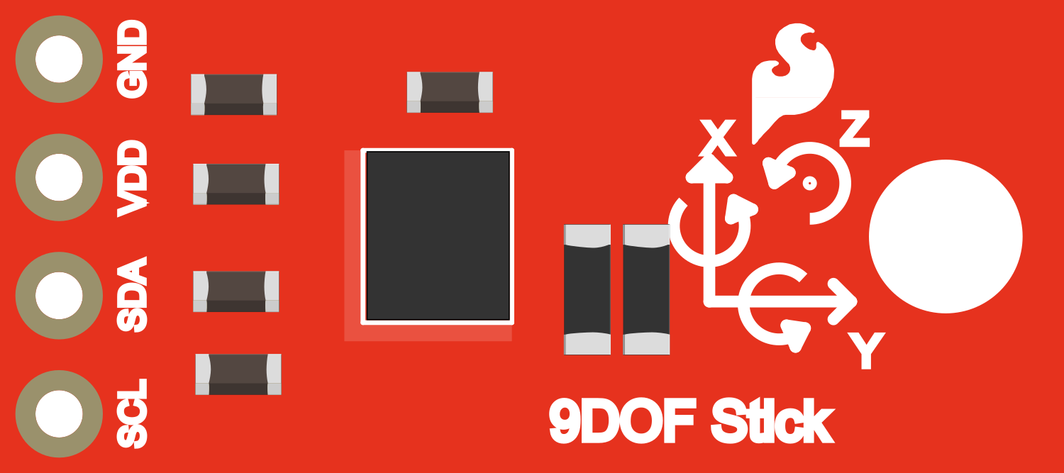
The SparkFun 9DoF (Degrees of Freedom) Sensor Stick is an all-in-one sensing module that combines a 3-axis accelerometer, a 3-axis gyroscope, and a 3-axis magnetometer. This compact sensor stick is capable of measuring linear acceleration, angular rotation velocity, and magnetic fields in all three dimensions. It is an ideal choice for applications in robotics, motion tracking, orientation detection, and more.

Explore Projects Built with SparkFun 9DoF Sensor Stick

Use Cirkit Designer to design, explore, and prototype these projects online. Some projects support real-time simulation. Click "Open Project" to start designing instantly!
ESP32-Based Motion Tracking System with ICM20948 Sensor
Image of ICM20948: A project utilizing SparkFun 9DoF Sensor Stick in a practical application
This circuit features a SparkFun ESP32 Thing Plus microcontroller interfaced with an Adafruit ICM20948 9-axis motion sensor via an Adafruit TXB0104 4-channel bi-directional level shifter. The ESP32 reads data from the ICM20948 sensor, calculates orientation angles such as pitch, roll, yaw, and azimuth, and outputs these values to the serial monitor. The level shifter ensures compatibility between the 3.3V logic levels of the ESP32 and the 1.8V logic levels required by the ICM20948.
Cirkit Designer LogoOpen Project in Cirkit Designer
Battery-Powered Arduino UNO with BNO085 IMU and Bluetooth HC-06 for Orientation Tracking
Image of bno085: A project utilizing SparkFun 9DoF Sensor Stick in a practical application
This circuit integrates an Arduino UNO with an Adafruit BNO085 9-DOF Orientation IMU and a Bluetooth HC-06 module. The Arduino reads orientation data from the IMU via I2C and transmits it over Bluetooth, powered by a 7.4V battery.
Cirkit Designer LogoOpen Project in Cirkit Designer
Arduino UNO-Based IMU and Bluetooth Communication System
Image of New one: A project utilizing SparkFun 9DoF Sensor Stick in a practical application
This circuit features an Arduino UNO microcontroller interfaced with a Bluetooth HC-06 module for wireless communication and an Adafruit BNO085 9-DOF Orientation IMU for motion sensing. The Arduino handles data acquisition from the IMU via I2C and communicates the data wirelessly through the Bluetooth module.
Cirkit Designer LogoOpen Project in Cirkit Designer
Raspberry Pi Zero-Based Sensor Hub with IMU and Flex Resistor
Image of Project: A project utilizing SparkFun 9DoF Sensor Stick in a practical application
This circuit integrates a Raspberry Pi Zero with an Adafruit ADS1115 16-bit ADC and an Adafruit BNO085 9-DOF Orientation IMU Fusion sensor. The Raspberry Pi reads analog signals from a flex resistor through the ADC and gathers orientation data from the IMU sensor, enabling it to process both analog and motion data.
Cirkit Designer LogoOpen Project in Cirkit Designer

Explore Projects Built with SparkFun 9DoF Sensor Stick

Use Cirkit Designer to design, explore, and prototype these projects online. Some projects support real-time simulation. Click "Open Project" to start designing instantly!
Image of ICM20948: A project utilizing SparkFun 9DoF Sensor Stick in a practical application
ESP32-Based Motion Tracking System with ICM20948 Sensor
This circuit features a SparkFun ESP32 Thing Plus microcontroller interfaced with an Adafruit ICM20948 9-axis motion sensor via an Adafruit TXB0104 4-channel bi-directional level shifter. The ESP32 reads data from the ICM20948 sensor, calculates orientation angles such as pitch, roll, yaw, and azimuth, and outputs these values to the serial monitor. The level shifter ensures compatibility between the 3.3V logic levels of the ESP32 and the 1.8V logic levels required by the ICM20948.
Cirkit Designer LogoOpen Project in Cirkit Designer
Image of bno085: A project utilizing SparkFun 9DoF Sensor Stick in a practical application
Battery-Powered Arduino UNO with BNO085 IMU and Bluetooth HC-06 for Orientation Tracking
This circuit integrates an Arduino UNO with an Adafruit BNO085 9-DOF Orientation IMU and a Bluetooth HC-06 module. The Arduino reads orientation data from the IMU via I2C and transmits it over Bluetooth, powered by a 7.4V battery.
Cirkit Designer LogoOpen Project in Cirkit Designer
Image of New one: A project utilizing SparkFun 9DoF Sensor Stick in a practical application
Arduino UNO-Based IMU and Bluetooth Communication System
This circuit features an Arduino UNO microcontroller interfaced with a Bluetooth HC-06 module for wireless communication and an Adafruit BNO085 9-DOF Orientation IMU for motion sensing. The Arduino handles data acquisition from the IMU via I2C and communicates the data wirelessly through the Bluetooth module.
Cirkit Designer LogoOpen Project in Cirkit Designer
Image of Project: A project utilizing SparkFun 9DoF Sensor Stick in a practical application
Raspberry Pi Zero-Based Sensor Hub with IMU and Flex Resistor
This circuit integrates a Raspberry Pi Zero with an Adafruit ADS1115 16-bit ADC and an Adafruit BNO085 9-DOF Orientation IMU Fusion sensor. The Raspberry Pi reads analog signals from a flex resistor through the ADC and gathers orientation data from the IMU sensor, enabling it to process both analog and motion data.
Cirkit Designer LogoOpen Project in Cirkit Designer

Technical Specifications

Key Technical Details

  • Accelerometer Range: ±2g/±4g/±8g/±16g (selectable)
  • Gyroscope Range: ±250°/s, ±500°/s, ±1000°/s, ±2000°/s (selectable)
  • Magnetometer Range: ±4800µT
  • Supply Voltage: 2.2V to 3.6V
  • Operating Current: 450µA (typical)
  • Communication Interface: I2C (up to 400kHz) and SPI (up to 10MHz)
  • Operating Temperature Range: -40°C to +85°C

Pin Configuration and Descriptions

Pin Number Name Description
1 GND Ground connection
2 VCC Supply voltage (2.2V to 3.6V)
3 SDA I2C data line / SPI data out (Master In Slave Out)
4 SCL I2C clock line / SPI clock
5 CS SPI chip select (active low)
6 SDO SPI data in (Master Out Slave In)
7 INT Interrupt pin (active low)

Usage Instructions

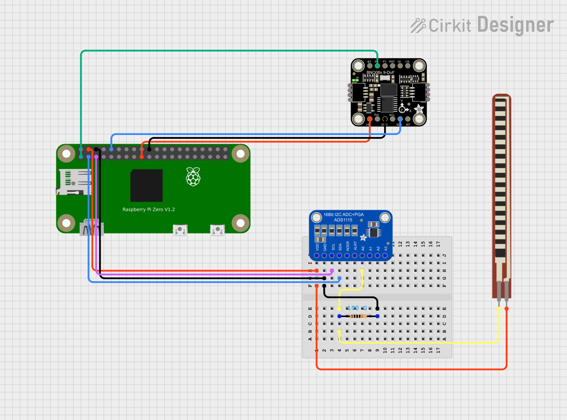
Integration with a Circuit

To use the SparkFun 9DoF Sensor Stick in a circuit:

  1. Connect the VCC pin to a power supply within the specified voltage range.
  2. Connect the GND pin to the ground of the power supply.
  3. For I2C communication, connect the SDA and SCL pins to the corresponding SDA and SCL pins on the microcontroller.
  4. For SPI communication, connect SDO, SDA, SCL, and CS to the MOSI, MISO, SCK, and SS pins on the microcontroller, respectively.
  5. Optionally, connect the INT pin to an interrupt-capable pin on the microcontroller to utilize the sensor's interrupt features.

Important Considerations and Best Practices

  • Ensure that the power supply voltage does not exceed the maximum rating of 3.6V.
  • Use pull-up resistors on the I2C data and clock lines if they are not already present on the microcontroller board.
  • When using SPI, ensure that the CS pin is driven high to low before starting communication and returned to high after communication is complete.
  • To minimize noise and ensure accurate readings, keep the sensor stick away from magnetic fields and vibration sources.

Example Code for Arduino UNO

#include <Wire.h>
#include <SparkFun_9DoF.h>

SparkFun_9DoF myIMU; // Create an instance of the 9DoF class

void setup() {
  Wire.begin(); // Initialize I2C
  Serial.begin(115200); // Start serial communication at 115200 baud

  if (myIMU.begin() == false) { // Check if the sensor is properly connected
    Serial.println("Device not connected. Please check connections.");
    while (1);
  }
}

void loop() {
  myIMU.readSensor(); // Read the sensor values

  // Print accelerometer values
  Serial.print("Accel X: ");
  Serial.print(myIMU.getAccelX_mss(), 4);
  Serial.print(" ");
  
  // Print gyroscope values
  Serial.print("Gyro X: ");
  Serial.print(myIMU.getGyroX_rads(), 4);
  Serial.print(" ");
  
  // Print magnetometer values
  Serial.print("Mag X: ");
  Serial.print(myIMU.getMagX_uT(), 4);
  Serial.println();

  delay(500); // Delay for readability
}

Troubleshooting and FAQs

Common Issues

  • Sensor not responding: Ensure that the wiring is correct and the power supply is within the specified voltage range.
  • Inaccurate readings: Calibrate the sensor as per the datasheet instructions and ensure it is placed away from magnetic fields and not subject to mechanical vibrations.
  • I2C communication failure: Check for proper pull-up resistors on the SDA and SCL lines and ensure there are no address conflicts on the I2C bus.

Solutions and Tips for Troubleshooting

  • Power Supply Issues: Use a multimeter to verify the voltage at the VCC pin.
  • Connection Issues: Double-check all connections, especially the SDA and SCL or SPI lines, for solid solder joints and correct wiring.
  • Code Debugging: Add serial print statements in your code to debug and verify that each section of your code is executing as expected.

FAQs

Q: Can I use multiple Sensor Sticks on the same I2C bus? A: Yes, but you will need to ensure each sensor has a unique I2C address. This can be done by altering the address if the sensor supports it or using an I2C multiplexer.

Q: How do I calibrate the magnetometer? A: Calibration typically involves rotating the sensor in various orientations and using the provided software tools or algorithms to compute the calibration parameters.

Q: What is the purpose of the INT pin? A: The INT pin can be used to trigger an interrupt on the microcontroller when certain conditions are met, such as a threshold being exceeded on any of the sensor axes.