How to Use L293D Motor Driver: Examples, Pinouts, and Specs
Introduction
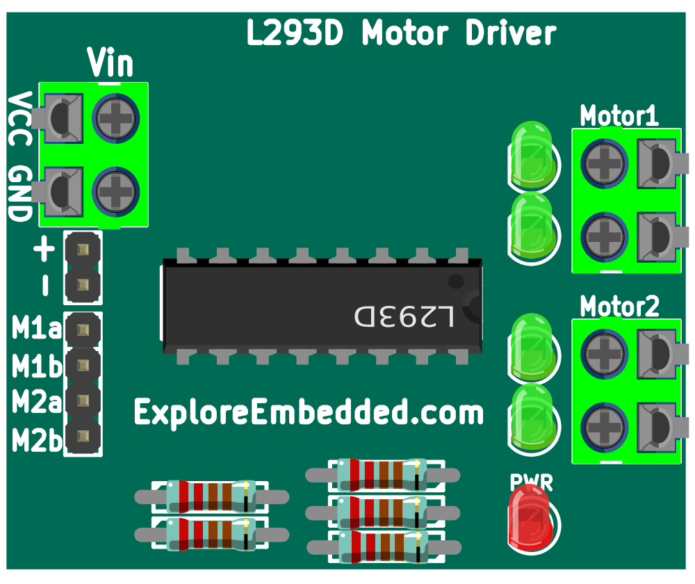
The L293D Motor Driver is an essential component for robotics and automation projects. It is designed to drive inductive loads such as relays, solenoids, DC, and stepping motors by allowing current to flow in both directions. This integrated circuit can control two DC motors simultaneously, making it a popular choice for dual-motor applications.
Explore Projects Built with L293D Motor Driver
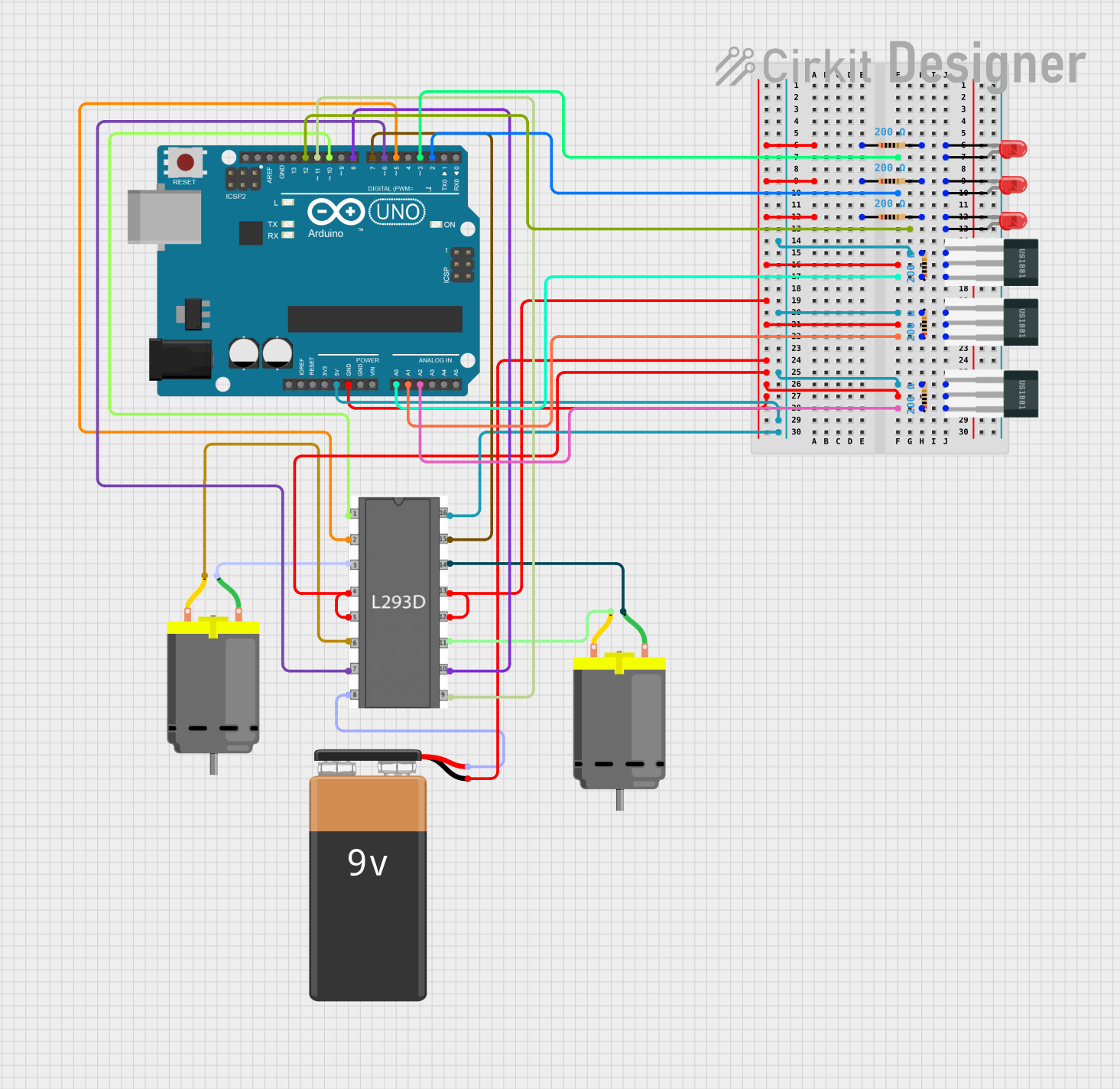
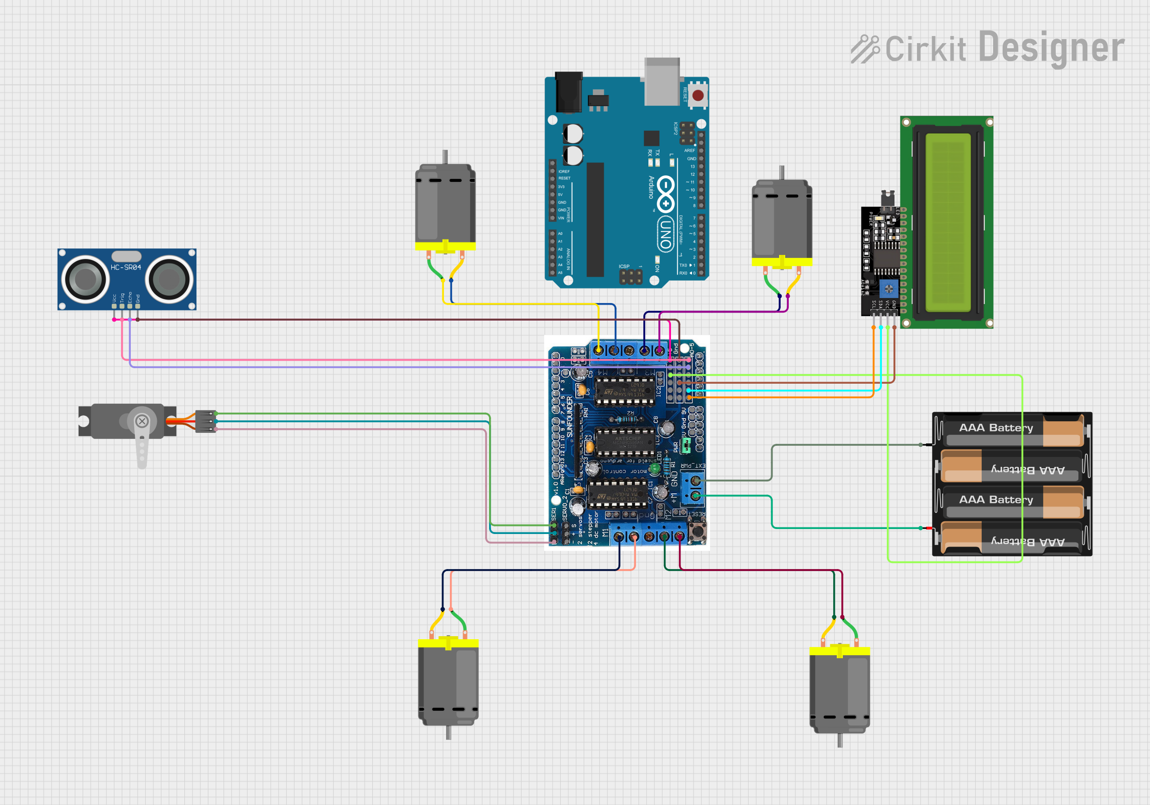

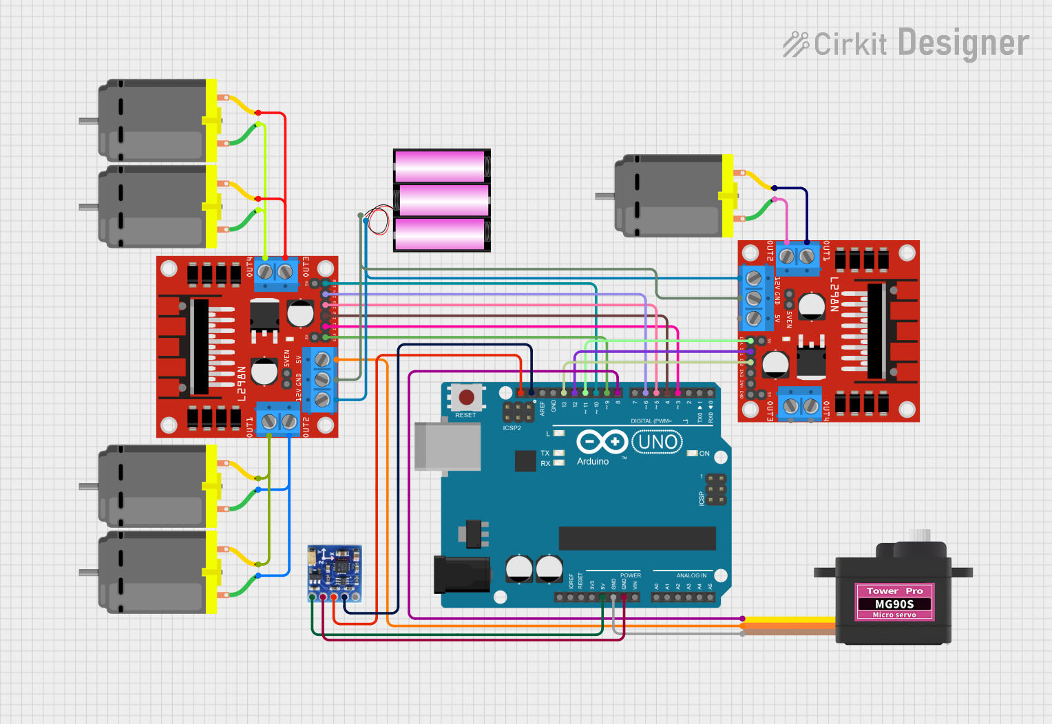
Explore Projects Built with L293D Motor Driver
Common Applications and Use Cases
- Robotics: Driving wheels or tracks
- Home automation: Controlling blinds or curtains
- Hobby projects: RC cars, boats, and drones
- Educational purposes: Teaching motor control principles
Technical Specifications
Key Technical Details
- Supply Voltage (Vcc1): 4.5V to 36V
- Supply Voltage for Motors (Vcc2): 4.5V to 36V
- Peak Output Current (per channel): 600mA
- Continuous Output Current (per channel): 300mA
- Input Logic Voltage: 4.5V to 7V (compatible with 5V logic levels)
- Internal Clamp Diodes for Back EMF Protection
- Power Dissipation: 4W
Pin Configuration and Descriptions
| Pin Number | Name | Description |
|---|---|---|
| 1 | 1,2EN | Enable pin for Motor 1 and 2; active high |
| 2 | 1A | Input 1 for Motor 1 |
| 3 | 1Y | Output 1 for Motor 1 |
| 4 | GND | Ground |
| 5 | GND | Ground |
| 6 | 2Y | Output 2 for Motor 1 |
| 7 | 2A | Input 2 for Motor 1 |
| 8 | Vcc2 | Motor supply voltage |
| 9 | 3,4EN | Enable pin for Motor 2; active high |
| 10 | 3A | Input 1 for Motor 2 |
| 11 | 3Y | Output 1 for Motor 2 |
| 12 | GND | Ground |
| 13 | GND | Ground |
| 14 | 4Y | Output 2 for Motor 2 |
| 15 | 4A | Input 2 for Motor 2 |
| 16 | Vcc1 | Logic supply voltage |
Usage Instructions
How to Use the L293D in a Circuit
- Connect Vcc1 to a 5V supply for the internal logic.
- Connect Vcc2 to the motor power supply, which can range from 4.5V to 36V.
- Connect the ground pins to the common ground of the circuit.
- Connect the enable pins (1,2EN and 3,4EN) to the logic level signals that will control the motor's operation.
- Connect the input pins (1A, 2A, 3A, 4A) to the microcontroller or digital logic circuit outputs.
- Connect the output pins (1Y, 2Y, 3Y, 4Y) to the motor terminals.
Important Considerations and Best Practices
- Use a separate power supply for Vcc2 if the motors require more current than the microcontroller can provide.
- Always use flyback diodes across the motors to protect the L293D from voltage spikes.
- Avoid running the motors at the peak current for extended periods to prevent thermal shutdown.
- Ensure that the enable pins are high to activate the motor driver channels.
Example Code for Arduino UNO
#include <Arduino.h>

// Define motor control pins
const int motor1Pin1 = 2; // Input 1 for Motor 1
const int motor1Pin2 = 3; // Input 2 for Motor 1
const int enableMotor1 = 9; // Enable pin for Motor 1

void setup() {
  // Set motor control pins as outputs
  pinMode(motor1Pin1, OUTPUT);
  pinMode(motor1Pin2, OUTPUT);
  pinMode(enableMotor1, OUTPUT);

  // Enable the motor
  digitalWrite(enableMotor1, HIGH);
}

void loop() {
  // Spin motor in one direction
  digitalWrite(motor1Pin1, HIGH);
  digitalWrite(motor1Pin2, LOW);
  delay(2000); // Run for 2 seconds

  // Stop the motor
  digitalWrite(motor1Pin1, LOW);
  digitalWrite(motor1Pin2, LOW);
  delay(1000); // Stop for 1 second

  // Spin motor in the opposite direction
  digitalWrite(motor1Pin1, LOW);
  digitalWrite(motor1Pin2, HIGH);
  delay(2000); // Run for 2 seconds

  // Stop the motor
  digitalWrite(motor1Pin1, LOW);
  digitalWrite(motor1Pin2, LOW);
  delay(1000); // Stop for 1 second
}
Troubleshooting and FAQs
Common Issues Users Might Face
- Motor not running: Check if the enable pin is set high and the input pins are correctly configured.
- Motor running weakly: Ensure the power supply for Vcc2 is adequate and the current is not exceeding the limit.
- Overheating: This could be due to running the motor at peak current for too long. Consider adding a heat sink.
Solutions and Tips for Troubleshooting
- Verify all connections and ensure that there are no loose wires.
- Measure the voltage at Vcc1 and Vcc2 to ensure they are within the specified range.
- Check the logic signals with an oscilloscope or logic analyzer to confirm they are being received by the L293D.
FAQs
Q: Can the L293D drive stepper motors? A: Yes, the L293D can drive a bipolar stepper motor by controlling the current in each coil in a sequence.
Q: What is the function of the enable pins? A: The enable pins turn the motor driver channels on or off. When high, the corresponding motor channel is active.
Q: Can I use the L293D with a 3.3V logic level microcontroller? A: While the L293D is designed for 5V logic levels, it may work with 3.3V logic; however, performance is not guaranteed. Consider using a level shifter for reliable operation.