
How to Use MAG3110: Examples, Pinouts, and Specs
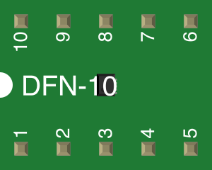
 Design with MAG3110 in Cirkit Designer
Introduction
The MAG3110, manufactured by NXP Semiconductors, is a high-performance digital magnetometer designed to measure magnetic fields in three dimensions (X, Y, and Z axes). Utilizing MEMS (Micro-Electro-Mechanical Systems) technology, the MAG3110 provides precise and reliable magnetic field measurements. Its compact size and low power consumption make it ideal for a wide range of applications, including navigation, robotics, geophysical exploration, and electronic compasses.
Explore Projects Built with MAG3110
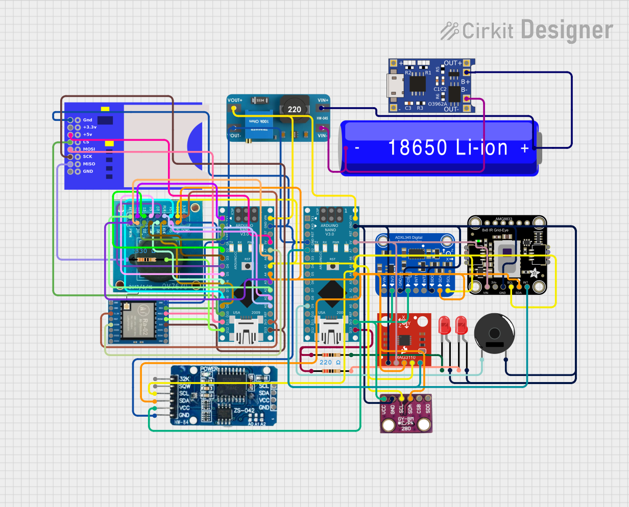 Open Project in Cirkit Designer
 Open Project in Cirkit Designer
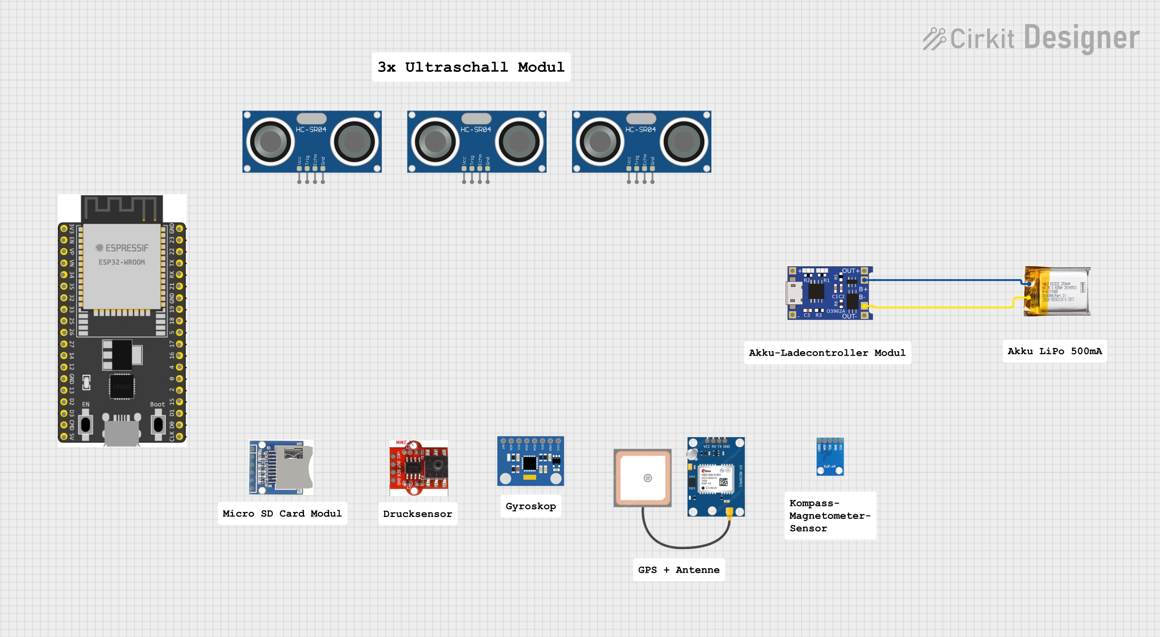 Open Project in Cirkit Designer
 Open Project in Cirkit Designer
Explore Projects Built with MAG3110
Open Project in Cirkit DesignerOpen Project in Cirkit DesignerOpen Project in Cirkit DesignerOpen Project in Cirkit DesignerCommon Applications:
- Navigation systems (e.g., electronic compasses)
- Robotics for orientation and positioning
- Geophysical exploration and mapping
- Consumer electronics (e.g., smartphones and wearables)
- Gaming and augmented reality (AR) devices
Technical Specifications
The MAG3110 is a versatile and efficient magnetometer with the following key specifications:
| Parameter | Value |
|---|---|
| Manufacturer | NXP Semiconductors |
| Part Number | MAG3110 |
| Measurement Range | ±1000 µT (microteslas) |
| Resolution | 0.1 µT |
| Communication Interface | I²C (Inter-Integrated Circuit) |
| Operating Voltage | 1.95V to 3.6V |
| Supply Current | 8.6 µA (typical in active mode) |
| Standby Current | 2 µA (typical) |
| Operating Temperature Range | -40°C to +85°C |
| Output Data Rate (ODR) | Up to 80 Hz |
| Package Type | 10-pin DFN (3 mm x 3 mm x 0.85 mm) |
Pin Configuration and Descriptions
The MAG3110 features a 10-pin DFN package. Below is the pin configuration and description:
| Pin Number | Pin Name | Description |
|---|---|---|
| 1 | VDD | Power supply input (1.95V to 3.6V) |
| 2 | GND | Ground |
| 3 | SCL | I²C clock line |
| 4 | SDA | I²C data line |
| 5 | INT1 | Interrupt 1 output |
| 6 | INT2 | Interrupt 2 output |
| 7-10 | NC | Not connected (leave unconnected) |
Usage Instructions
The MAG3110 is straightforward to integrate into a circuit, thanks to its I²C interface. Below are the steps and best practices for using the component:
Connecting the MAG3110
- Power Supply: Connect the VDD pin to a 3.3V power source (or within the operating voltage range of 1.95V to 3.6V). Connect the GND pin to the ground of the circuit.
- I²C Communication:
- Connect the SCL pin to the I²C clock line of your microcontroller.
- Connect the SDA pin to the I²C data line of your microcontroller.
- Use pull-up resistors (typically 4.7 kΩ) on both the SCL and SDA lines.
- Interrupts (Optional): If you need to use interrupts, connect INT1 and/or INT2 to the appropriate interrupt pins on your microcontroller.
Example Code for Arduino UNO
Below is an example of how to interface the MAG3110 with an Arduino UNO using the I²C protocol:
#include <Wire.h> // Include the Wire library for I²C communication

#define MAG3110_ADDRESS 0x0E // I²C address of the MAG3110

void setup() {
  Wire.begin(); // Initialize I²C communication
  Serial.begin(9600); // Initialize serial communication for debugging

  // Configure the MAG3110
  Wire.beginTransmission(MAG3110_ADDRESS);
  Wire.write(0x10); // CTRL_REG1 register address
  Wire.write(0x01); // Set active mode with 80 Hz ODR
  Wire.endTransmission();

  Serial.println("MAG3110 initialized.");
}

void loop() {
  int16_t x, y, z;

  // Request data from the MAG3110
  Wire.beginTransmission(MAG3110_ADDRESS);
  Wire.write(0x01); // Address of the X-axis MSB register
  Wire.endTransmission(false);
  Wire.requestFrom(MAG3110_ADDRESS, 6); // Request 6 bytes (X, Y, Z)

  // Read the data
  if (Wire.available() == 6) {
    x = (Wire.read() << 8) | Wire.read(); // Combine MSB and LSB for X-axis
    y = (Wire.read() << 8) | Wire.read(); // Combine MSB and LSB for Y-axis
    z = (Wire.read() << 8) | Wire.read(); // Combine MSB and LSB for Z-axis
  }

  // Print the magnetic field values
  Serial.print("X: ");
  Serial.print(x);
  Serial.print(" Y: ");
  Serial.print(y);
  Serial.print(" Z: ");
  Serial.println(z);

  delay(100); // Delay for readability
}
Best Practices
- Ensure proper decoupling by placing a 0.1 µF capacitor close to the VDD pin.
- Use appropriate pull-up resistors on the I²C lines to ensure reliable communication.
- Avoid placing the MAG3110 near strong magnetic sources or ferromagnetic materials to prevent interference.
- Calibrate the sensor in your application to account for environmental magnetic distortions.
Troubleshooting and FAQs
Common Issues and Solutions
No Data Output:
- Ensure the MAG3110 is powered correctly (check VDD and GND connections).
- Verify the I²C pull-up resistors are properly connected.
- Check the I²C address (default is 0x0E) and ensure it matches your code.
Inaccurate Measurements:
- Perform a calibration routine to account for hard and soft iron distortions.
- Ensure the sensor is not placed near strong magnetic fields or ferromagnetic materials.
I²C Communication Errors:
- Check the SCL and SDA connections for continuity.
- Ensure the I²C clock speed is within the supported range of the MAG3110.
FAQs
Q: Can the MAG3110 measure the Earth's magnetic field?
A: Yes, the MAG3110 is capable of measuring the Earth's magnetic field, making it suitable for applications like electronic compasses and navigation systems.
Q: What is the maximum distance for I²C communication with the MAG3110?
A: The maximum distance depends on the pull-up resistor values and the capacitance of the I²C bus. Typically, I²C is reliable for short distances (up to a few meters).
Q: How do I calibrate the MAG3110?
A: Calibration involves rotating the sensor in all directions to collect data and then applying algorithms to compensate for hard and soft iron distortions. Many libraries and tools are available to assist with this process.
Q: Can the MAG3110 operate at 5V?
A: No, the MAG3110 operates within a voltage range of 1.95V to 3.6V. Use a voltage regulator or level shifter if interfacing with a 5V system.
By following this documentation, you can effectively integrate and utilize the MAG3110 in your projects.