Cirkit Designer
Your all-in-one circuit design IDE
Home /
Component Documentation
How to Use Anti reverse diode: Examples, Pinouts, and Specs
Introduction
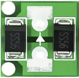
The Anti-Reverse Diode, specifically the Schottky Barrier Rectifier from CN, is a crucial component in electronic circuits designed to prevent current from flowing in the reverse direction. This protection mechanism is essential for safeguarding circuits from potential damage due to reverse polarity. Schottky diodes are known for their low forward voltage drop and fast switching capabilities, making them ideal for various applications.
Explore Projects Built with Anti reverse diode
Rectifier Diode and LED Circuit with Rocker Switch Control
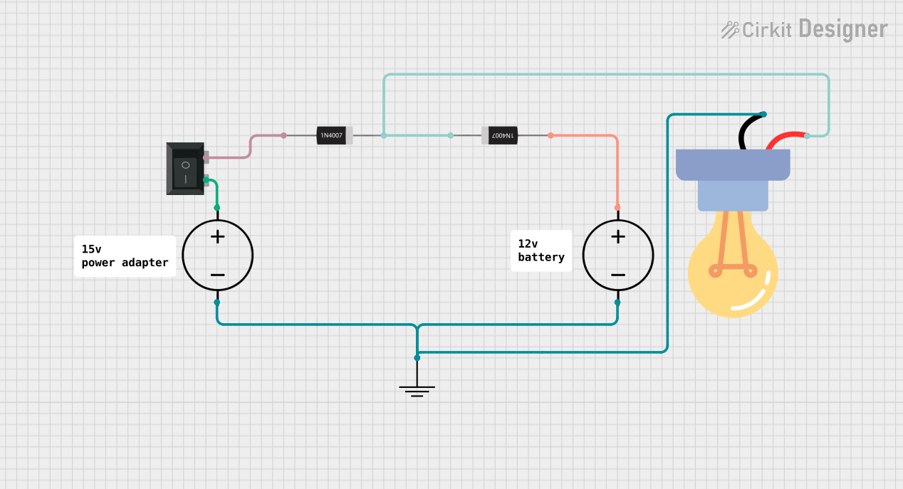
This circuit appears to be a simple power supply circuit with a protection diode and an LED indicator. The diode ensures current flows in only one direction, protecting the circuit from reverse polarity damage. A rocker switch is used to control the power to the LED, which likely serves as an indicator for when the power is on.
Resistor-Diode Circuit with Multimeter Current Measurement
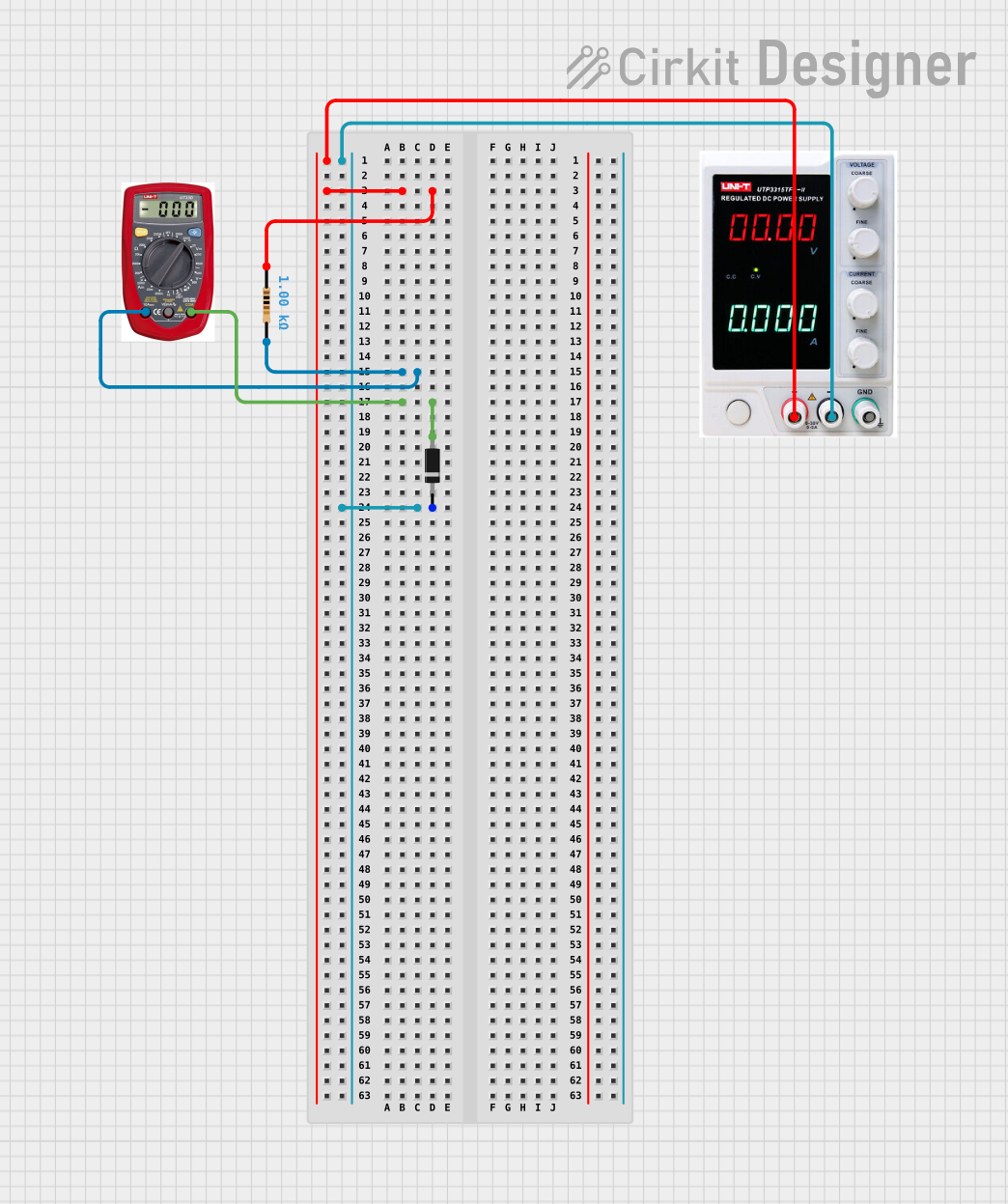
This circuit consists of a power supply connected in series with a resistor and a diode. A multimeter is connected across the resistor to measure the current flowing through the resistor. The diode ensures current flows in one direction, protecting the circuit from potential reverse current damage.
Diode and Capacitor-Based Voltage Regulation Circuit

This circuit is a complex network of diodes and electrolytic capacitors connected to two terminal PCB 2-pin connectors. The diodes are arranged in a series-parallel configuration, while the capacitors are connected in a manner that suggests filtering or energy storage purposes. The overall design appears to be aimed at rectification and smoothing of an input signal.
12V to 5V Power Supply with LED Indicator and Push Switch

This circuit is a 12V to 5V regulated power supply with an LED indicator. It uses a 5408 diode for reverse polarity protection, an LM340T5 7805 voltage regulator to step down the voltage to 5V, and a push switch to control the LED indicator. The circuit also includes capacitors for filtering and a resistor to limit the current through the LED.
Explore Projects Built with Anti reverse diode
Rectifier Diode and LED Circuit with Rocker Switch Control
This circuit appears to be a simple power supply circuit with a protection diode and an LED indicator. The diode ensures current flows in only one direction, protecting the circuit from reverse polarity damage. A rocker switch is used to control the power to the LED, which likely serves as an indicator for when the power is on.
Resistor-Diode Circuit with Multimeter Current Measurement
This circuit consists of a power supply connected in series with a resistor and a diode. A multimeter is connected across the resistor to measure the current flowing through the resistor. The diode ensures current flows in one direction, protecting the circuit from potential reverse current damage.
Diode and Capacitor-Based Voltage Regulation Circuit
This circuit is a complex network of diodes and electrolytic capacitors connected to two terminal PCB 2-pin connectors. The diodes are arranged in a series-parallel configuration, while the capacitors are connected in a manner that suggests filtering or energy storage purposes. The overall design appears to be aimed at rectification and smoothing of an input signal.
12V to 5V Power Supply with LED Indicator and Push Switch
This circuit is a 12V to 5V regulated power supply with an LED indicator. It uses a 5408 diode for reverse polarity protection, an LM340T5 7805 voltage regulator to step down the voltage to 5V, and a push switch to control the LED indicator. The circuit also includes capacitors for filtering and a resistor to limit the current through the LED.
Common Applications and Use Cases
- Power Supply Protection: Prevents damage to power supplies by blocking reverse current.
- Battery Protection: Ensures batteries are not damaged by reverse polarity connections.
- Solar Panels: Protects solar panels from reverse current during low light conditions.
- DC Motors: Prevents reverse current that could damage motor windings.
Technical Specifications
Key Technical Details
| Parameter | Value |
|---|---|
| Manufacturer | CN |
| Part ID | SCHOTTKY BARRIER RECTIFIER |
| Forward Voltage Drop | 0.2V to 0.45V |
| Maximum Current | 1A to 3A |
| Reverse Voltage | 20V to 100V |
| Package Type | DO-41, SOD-123, SOD-323 |
| Operating Temperature | -55°C to +150°C |
Pin Configuration and Descriptions
| Pin Number | Pin Name | Description |
|---|---|---|
| 1 | Anode | Positive terminal of the diode |
| 2 | Cathode | Negative terminal of the diode |
Usage Instructions
How to Use the Component in a Circuit
- Identify the Anode and Cathode: The anode is typically marked with a positive sign (+) or a longer lead, while the cathode is marked with a negative sign (-) or a shorter lead.
- Connect the Anode to the Positive Voltage Source: Ensure the anode is connected to the positive side of the power supply.
- Connect the Cathode to the Load: The cathode should be connected to the load or the negative side of the circuit.
- Verify Connections: Double-check all connections to ensure the diode is correctly oriented to prevent reverse current.
Important Considerations and Best Practices
- Heat Dissipation: Ensure adequate heat dissipation, especially in high-current applications, to prevent thermal damage.
- Voltage Ratings: Always check the reverse voltage rating to ensure it exceeds the maximum voltage in your circuit.
- Current Ratings: Ensure the diode's current rating is sufficient for your application to avoid overloading.
Example Circuit with Arduino UNO
/*
  Example code to demonstrate the use of an Anti-Reverse Diode
  with an Arduino UNO. This code assumes the diode is used to
  protect the Arduino from reverse polarity on the power supply.
*/

void setup() {
  // Initialize serial communication at 9600 baud rate
  Serial.begin(9600);

  // Set pin 13 as an output to control an LED
  pinMode(13, OUTPUT);
}

void loop() {
  // Turn the LED on
  digitalWrite(13, HIGH);
  Serial.println("LED is ON");

  // Wait for 1 second
  delay(1000);

  // Turn the LED off
  digitalWrite(13, LOW);
  Serial.println("LED is OFF");

  // Wait for 1 second
  delay(1000);
}
Troubleshooting and FAQs
Common Issues Users Might Face
Diode Overheating:
- Cause: Excessive current or inadequate heat dissipation.
- Solution: Ensure the current does not exceed the diode's rating and provide proper heat sinks if necessary.
Incorrect Orientation:
- Cause: Anode and cathode are reversed.
- Solution: Double-check the orientation and ensure the anode is connected to the positive voltage source.
Voltage Drop Issues:
- Cause: Forward voltage drop too high for the application.
- Solution: Choose a Schottky diode with a lower forward voltage drop.
Solutions and Tips for Troubleshooting
- Check Connections: Always verify that all connections are secure and correctly oriented.
- Measure Voltage: Use a multimeter to measure the voltage across the diode to ensure it is within the expected range.
- Consult Datasheets: Refer to the manufacturer's datasheet for detailed specifications and guidelines.
By following this documentation, users can effectively utilize the Anti-Reverse Diode (Schottky Barrier Rectifier) from CN to protect their electronic circuits from reverse polarity damage.