How to Use RF Link Receiver - 4800bps (434MHz): Examples, Pinouts, and Specs
Introduction
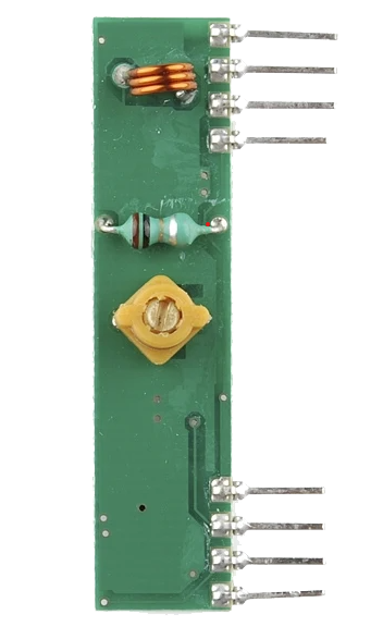
The RF Link Receiver - 4800bps (434MHz), manufactured by WENSHING (Part ID: RF_RX_434), is a compact and efficient radio frequency receiver module. It is designed to receive data signals at a baud rate of 4800 bps and operates at a frequency of 434 MHz. This module is widely used in wireless communication systems for applications such as remote controls, data transmission, and IoT devices.
Explore Projects Built with RF Link Receiver - 4800bps (434MHz)


Explore Projects Built with RF Link Receiver - 4800bps (434MHz)
Common Applications
- Wireless remote controls (e.g., garage doors, home automation)
- IoT devices and sensor networks
- Wireless data transmission between microcontrollers
- Robotics and automation systems
- Security systems and alarms
Technical Specifications
The following table outlines the key technical details of the RF Link Receiver:
| Parameter | Value |
|---|---|
| Operating Frequency | 434 MHz |
| Baud Rate | 4800 bps |
| Operating Voltage | 5V DC |
| Current Consumption | 4.5 mA (typical) |
| Sensitivity | -105 dBm |
| Modulation Type | ASK (Amplitude Shift Keying) |
| Operating Temperature | -20°C to +70°C |
| Dimensions | 30mm x 14mm x 7mm |
Pin Configuration and Descriptions
The RF Link Receiver module has 4 pins, as described in the table below:
| Pin | Name | Description |
|---|---|---|
| 1 | VCC | Power supply input (5V DC). Connect to a regulated 5V power source. |
| 2 | DATA | Data output pin. Outputs the received digital signal. |
| 3 | GND | Ground pin. Connect to the ground of the power supply and circuit. |
| 4 | ANT | Antenna connection. Attach a 17cm wire or a proper 434 MHz antenna for optimal reception. |
Usage Instructions
How to Use the RF Link Receiver in a Circuit
- Power Supply: Connect the VCC pin to a regulated 5V DC power source and the GND pin to the ground.
- Antenna: Attach a 17cm wire or a 434 MHz antenna to the ANT pin for better signal reception.
- Data Output: Connect the DATA pin to the input pin of a microcontroller (e.g., Arduino) or a decoder IC to process the received signal.
- Pairing with a Transmitter: Ensure the RF transmitter module operates at the same frequency (434 MHz) and baud rate (4800 bps) for proper communication.
Important Considerations and Best Practices
- Antenna Placement: For optimal performance, place the antenna in an open area, away from metal objects or interference sources.
- Power Supply: Use a stable and noise-free 5V power supply to avoid signal distortion.
- Decoding Data: The received signal may need to be decoded using a microcontroller or a dedicated decoder IC, depending on the application.
- Range: The effective range of the module depends on environmental factors, such as obstacles and interference. Ensure a clear line of sight for maximum range.
Example: Connecting to an Arduino UNO
Below is an example of how to connect the RF Link Receiver to an Arduino UNO and read the received data:
Circuit Connections
- VCC: Connect to the Arduino's 5V pin.
- GND: Connect to the Arduino's GND pin.
- DATA: Connect to Arduino digital pin 2.
- ANT: Attach a 17cm wire to the ANT pin.
Arduino Code Example
// Example code to read data from the RF Link Receiver (RF_RX_434)
// Connect the DATA pin of the receiver to Arduino digital pin 2

#define RECEIVER_PIN 2  // Define the pin connected to the DATA pin of the receiver

void setup() {
  Serial.begin(9600);  // Initialize serial communication at 9600 bps
  pinMode(RECEIVER_PIN, INPUT);  // Set the receiver pin as input
  Serial.println("RF Receiver Ready");
}

void loop() {
  int receivedData = digitalRead(RECEIVER_PIN);  // Read the data from the receiver
  Serial.print("Received Data: ");
  Serial.println(receivedData);  // Print the received data to the Serial Monitor
  delay(100);  // Small delay to avoid flooding the Serial Monitor
}
Note: The received data may need further processing or decoding, depending on the transmitter's encoding scheme.
Troubleshooting and FAQs
Common Issues and Solutions
No Data Received
- Cause: Incorrect wiring or power supply issues.
- Solution: Double-check all connections and ensure the module is powered with a stable 5V supply.
Poor Signal Reception
- Cause: Antenna not properly connected or interference from nearby devices.
- Solution: Attach a 17cm wire to the ANT pin and ensure the module is placed away from interference sources.
Data Corruption
- Cause: Mismatched baud rate or noisy power supply.
- Solution: Verify that the transmitter and receiver are operating at the same baud rate (4800 bps). Use a clean and regulated power supply.
Short Range
- Cause: Obstacles or improper antenna placement.
- Solution: Ensure a clear line of sight between the transmitter and receiver. Use a proper 434 MHz antenna for better range.
FAQs
Q1: Can I use this module with a 3.3V microcontroller?
A1: The RF Link Receiver requires a 5V power supply. However, the DATA pin output can be connected to a 3.3V microcontroller if the logic level is compatible.
Q2: What is the maximum range of this module?
A2: The range depends on environmental factors but typically varies between 50-100 meters in open areas.
Q3: Can I use multiple receivers with a single transmitter?
A3: Yes, multiple receivers can be used with a single transmitter, provided they operate at the same frequency and baud rate.
Q4: Do I need an external decoder IC?
A4: It depends on your application. For simple data transmission, a microcontroller can process the received signal. For more complex protocols, a dedicated decoder IC may be required.