
How to Use 134.2K RFID Reader Module: Examples, Pinouts, and Specs
 Design with 134.2K RFID Reader Module in Cirkit Designer
Introduction
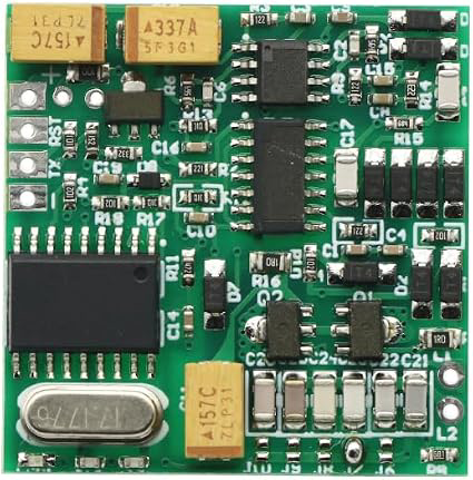
The 134.2K RFID Reader Module (Manufacturer: Generic, Part ID: 9524286427180) is a device designed to read RFID tags operating at a frequency of 134.2 kHz. This module is widely used in applications such as access control systems, inventory management, pet identification, and asset tracking. It provides a reliable and efficient way to identify and track objects or animals equipped with compatible RFID tags.
This module is compact, easy to integrate into various systems, and supports communication with microcontrollers like Arduino, Raspberry Pi, and other embedded platforms.
Explore Projects Built with 134.2K RFID Reader Module
 Open Project in Cirkit Designer
 Open Project in Cirkit Designer
 Open Project in Cirkit Designer
 Open Project in Cirkit Designer
Explore Projects Built with 134.2K RFID Reader Module
Open Project in Cirkit DesignerOpen Project in Cirkit DesignerOpen Project in Cirkit DesignerOpen Project in Cirkit DesignerTechnical Specifications
Below are the key technical details of the 134.2K RFID Reader Module:
General Specifications
| Parameter | Value |
|---|---|
| Operating Frequency | 134.2 kHz |
| Communication Protocol | UART (TTL level) |
| Operating Voltage | 5V DC |
| Operating Current | ≤ 50 mA |
| Reading Distance | Up to 10 cm (depending on tag) |
| Supported Tags | ISO 11784/11785 compliant |
| Dimensions | 60 mm x 40 mm x 5 mm |
| Operating Temperature | -20°C to +70°C |
Pin Configuration
The module typically has a 4-pin interface for communication and power. The pinout is as follows:
| Pin Number | Pin Name | Description |
|---|---|---|
| 1 | VCC | Power supply input (5V DC) |
| 2 | GND | Ground connection |
| 3 | TX | UART Transmit pin (data output) |
| 4 | RX | UART Receive pin (data input, for configuration) |
Usage Instructions
Connecting the Module
To use the 134.2K RFID Reader Module in a circuit, follow these steps:
- Power the Module: Connect the
VCCpin to a 5V DC power source and theGNDpin to the ground. - Establish Communication: Connect the
TXpin of the module to theRXpin of your microcontroller (e.g., Arduino UNO). Optionally, connect theRXpin of the module to theTXpin of the microcontroller if configuration commands are required. - Place RFID Tags: Ensure the RFID tag is within the module's reading range (up to 10 cm).
Arduino UNO Example Code
Below is an example of how to interface the module with an Arduino UNO to read RFID tag data:
// Example code for interfacing the 134.2K RFID Reader Module with Arduino UNO
// Connect the module's TX pin to Arduino pin 10 (RX) for data reception.

#include <SoftwareSerial.h>

// Define software serial pins for communication with the RFID module
SoftwareSerial RFID(10, 11); // RX = pin 10, TX = pin 11 (not used in this example)

void setup() {
  Serial.begin(9600);       // Initialize Serial Monitor at 9600 baud
  RFID.begin(9600);         // Initialize RFID module communication at 9600 baud
  Serial.println("134.2K RFID Reader Module Ready");
}

void loop() {
  if (RFID.available()) {   // Check if data is available from the RFID module
    String tagData = "";    // Variable to store the tag data
    while (RFID.available()) {
      char c = RFID.read(); // Read each character from the module
      tagData += c;         // Append the character to the tagData string
    }
    Serial.print("RFID Tag Data: ");
    Serial.println(tagData); // Print the tag data to the Serial Monitor
  }
}
Important Considerations
- Ensure the RFID tag is ISO 11784/11785 compliant for compatibility.
- Avoid placing the module near strong electromagnetic interference sources, as this may affect performance.
- Use proper pull-up resistors if required for UART communication stability.
- Maintain a stable 5V power supply to avoid communication errors.
Troubleshooting and FAQs
Common Issues and Solutions
No Data Received from the Module
- Solution: Verify the wiring connections, especially the
TXpin of the module to theRXpin of the microcontroller. - Solution: Ensure the RFID tag is within the module's reading range (up to 10 cm).
- Solution: Verify the wiring connections, especially the
Incorrect or Garbled Data
- Solution: Check that the baud rate of the microcontroller matches the module's default baud rate (9600 bps).
- Solution: Ensure the power supply is stable and noise-free.
Module Not Powering On
- Solution: Confirm that the
VCCpin is connected to a 5V DC source and theGNDpin is properly grounded.
- Solution: Confirm that the
FAQs
Q1: Can this module read multiple tags simultaneously?
A1: No, the module reads one tag at a time. Ensure only one tag is within the reading range.
Q2: Can I use this module with a 3.3V microcontroller?
A2: Yes, but you will need a level shifter to safely interface the 5V TX signal with the 3.3V microcontroller.
Q3: What is the maximum cable length for UART communication?
A3: For reliable communication, keep the cable length under 1 meter. Use shielded cables for longer distances.
Q4: How do I configure the module's settings?
A4: The module supports configuration via UART commands. Refer to the manufacturer's datasheet for details.
By following this documentation, you can effectively integrate and troubleshoot the 134.2K RFID Reader Module in your projects.