How to Use Mạch sạc 18650 : Examples, Pinouts, and Specs
Introduction
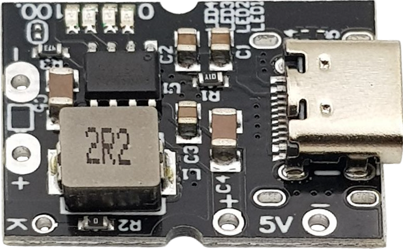
The Mạch sạc 18650 is a battery charging circuit specifically designed for safely charging lithium-ion 18650 cells. It is equipped with essential safety features such as overcharge protection, temperature monitoring, and charging status indicators. This component ensures efficient and reliable charging, making it ideal for applications requiring rechargeable power sources.
Explore Projects Built with Mạch sạc 18650


Explore Projects Built with Mạch sạc 18650
Common Applications and Use Cases
- Power banks and portable chargers
- DIY electronics projects
- Robotics and IoT devices
- Flashlights and other battery-powered tools
- Renewable energy storage systems
Technical Specifications
Key Technical Details
- Input Voltage: 5V DC (via micro-USB or solder pads)
- Charging Current: Typically 1A (adjustable in some models)
- Battery Type: Lithium-ion 18650 cells (3.7V nominal, 4.2V fully charged)
- Overcharge Protection: Stops charging at 4.2V ± 1%
- Over-discharge Protection: Disconnects load at ~2.5V
- Temperature Monitoring: Built-in thermistor (optional, depending on model)
- Charging Status Indicators: LED indicators for charging (red) and fully charged (blue/green)
Pin Configuration and Descriptions
| Pin/Connector | Description |
|---|---|
| IN+ | Positive input terminal for 5V DC power supply (via solder pad or micro-USB). |
| IN- | Negative input terminal for 5V DC power supply (via solder pad or micro-USB). |
| B+ | Positive terminal for connecting the 18650 battery. |
| B- | Negative terminal for connecting the 18650 battery. |
| OUT+ | Positive output terminal for powering external circuits (connected to battery). |
| OUT- | Negative output terminal for powering external circuits (connected to battery). |
Usage Instructions
How to Use the Mạch sạc 18650 in a Circuit
- Power Input: Connect a 5V DC power source to the
IN+andIN-pins. You can use a micro-USB cable or solder wires directly to the input pads. - Battery Connection: Connect the 18650 battery to the
B+andB-terminals. Ensure correct polarity to avoid damage. - Output Connection: If you need to power an external circuit, connect it to the
OUT+andOUT-terminals. The output voltage will match the battery voltage. - Charging Status: Observe the LED indicators:
- Red LED: Charging in progress.
- Blue/Green LED: Charging complete.
- Safety Features: The circuit will automatically stop charging when the battery reaches 4.2V and disconnect the load if the battery voltage drops below ~2.5V.
Important Considerations and Best Practices
- Battery Compatibility: Only use 18650 lithium-ion cells. Do not use other battery types.
- Heat Management: Ensure proper ventilation to prevent overheating during charging.
- Current Adjustment: If your module supports adjustable charging current, set it according to the battery's specifications (e.g., 0.5C to 1C of the battery capacity).
- Avoid Overloading: Do not connect loads that exceed the circuit's current rating.
- Polarity Check: Double-check all connections to avoid reverse polarity damage.
Example: Using with Arduino UNO
The Mạch sạc 18650 can be used to power an Arduino UNO. Here's an example of connecting the circuit:
- Connect the
OUT+andOUT-terminals of the charging module to the Arduino'sVINandGNDpins, respectively. - Ensure the battery is fully charged before powering the Arduino.
Sample Code for Monitoring Battery Voltage
You can monitor the battery voltage using the Arduino's analog input:
const int batteryPin = A0; // Connect OUT+ to A0 via a voltage divider
float voltage = 0.0;

void setup() {
  Serial.begin(9600);
}

void loop() {
  int sensorValue = analogRead(batteryPin);
  // Convert the analog reading to voltage (assuming a 10k:10k voltage divider)
  voltage = (sensorValue * 5.0 / 1023.0) * 2;
  // Multiply by 2 because of the voltage divider ratio
  Serial.print("Battery Voltage: ");
  Serial.print(voltage);
  Serial.println(" V");
  delay(1000);
}
Note: Use a voltage divider (e.g., two 10k resistors) to scale the battery voltage to a safe range for the Arduino's analog input.
Troubleshooting and FAQs
Common Issues and Solutions
LEDs Not Lighting Up
- Cause: No power input or incorrect connections.
- Solution: Verify the 5V power source and check all connections for proper polarity.
Battery Not Charging
- Cause: Faulty battery or loose connections.
- Solution: Test the battery with a multimeter and ensure secure connections to
B+andB-.
Overheating During Charging
- Cause: High ambient temperature or insufficient ventilation.
- Solution: Place the module in a well-ventilated area and avoid charging in hot environments.
Output Voltage Too Low
- Cause: Battery is deeply discharged or damaged.
- Solution: Replace the battery if it cannot hold a charge above 2.5V.
FAQs
Can I use this module with other lithium-ion batteries?
- This module is optimized for 18650 cells. Using other batteries may require additional adjustments or may not be safe.
What happens if I connect the battery with reverse polarity?
- Most modules include reverse polarity protection, but it's best to avoid this as it may still damage the circuit.
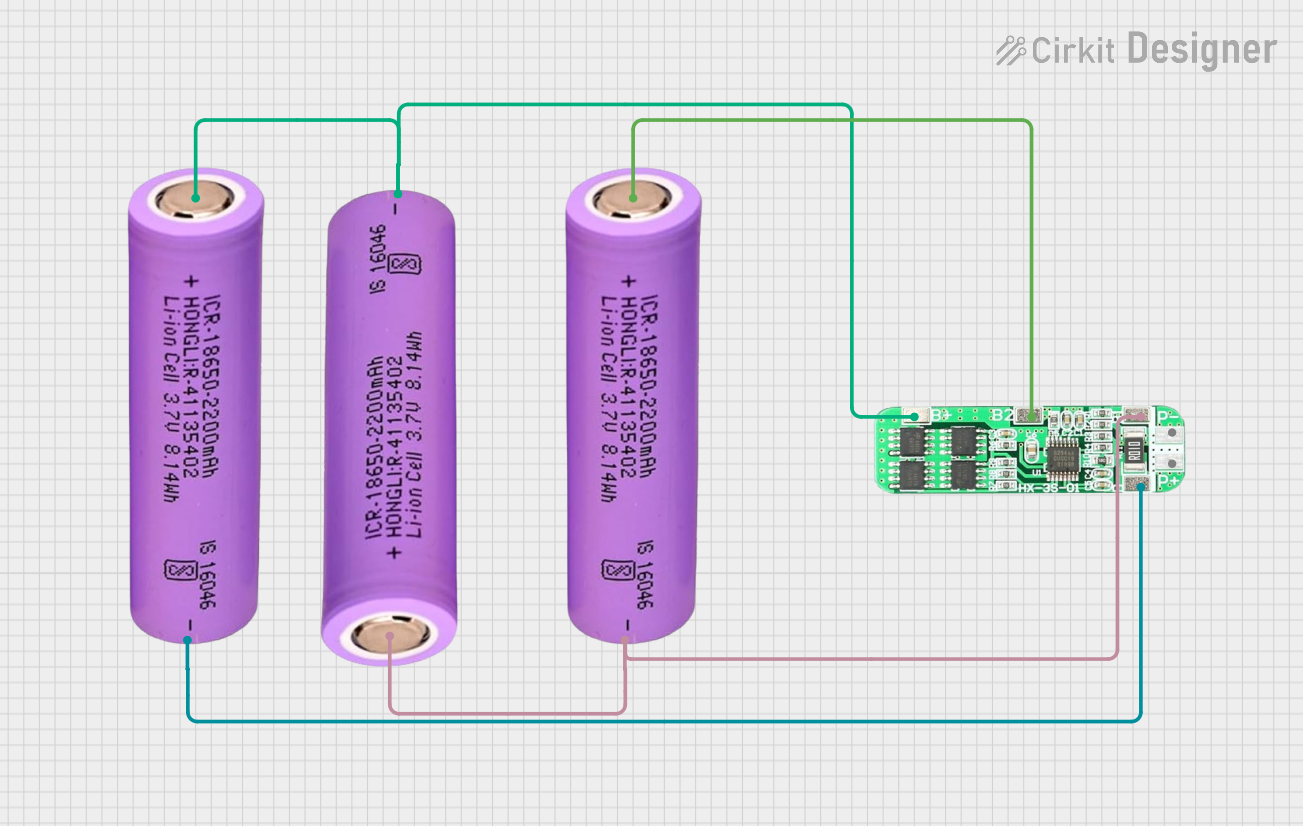
Can I charge multiple 18650 cells in parallel?
- Yes, but ensure the cells are balanced and have the same charge level before connecting them in parallel.
Is it safe to leave the battery connected after charging?
- Yes, the module includes overcharge protection, but it's good practice to disconnect the battery when not in use.