How to Use Module Sim a7680c: Examples, Pinouts, and Specs
Introduction
The Module Sim a7680c, developed by Arduino, is a versatile simulation module designed for testing and analyzing electronic circuits. It provides a robust platform for simulating various circuit configurations and behaviors, enabling engineers and hobbyists to optimize their designs before physical implementation. This module is particularly useful in prototyping, educational environments, and research applications where circuit behavior needs to be evaluated without the need for physical components.
Explore Projects Built with Module Sim a7680c

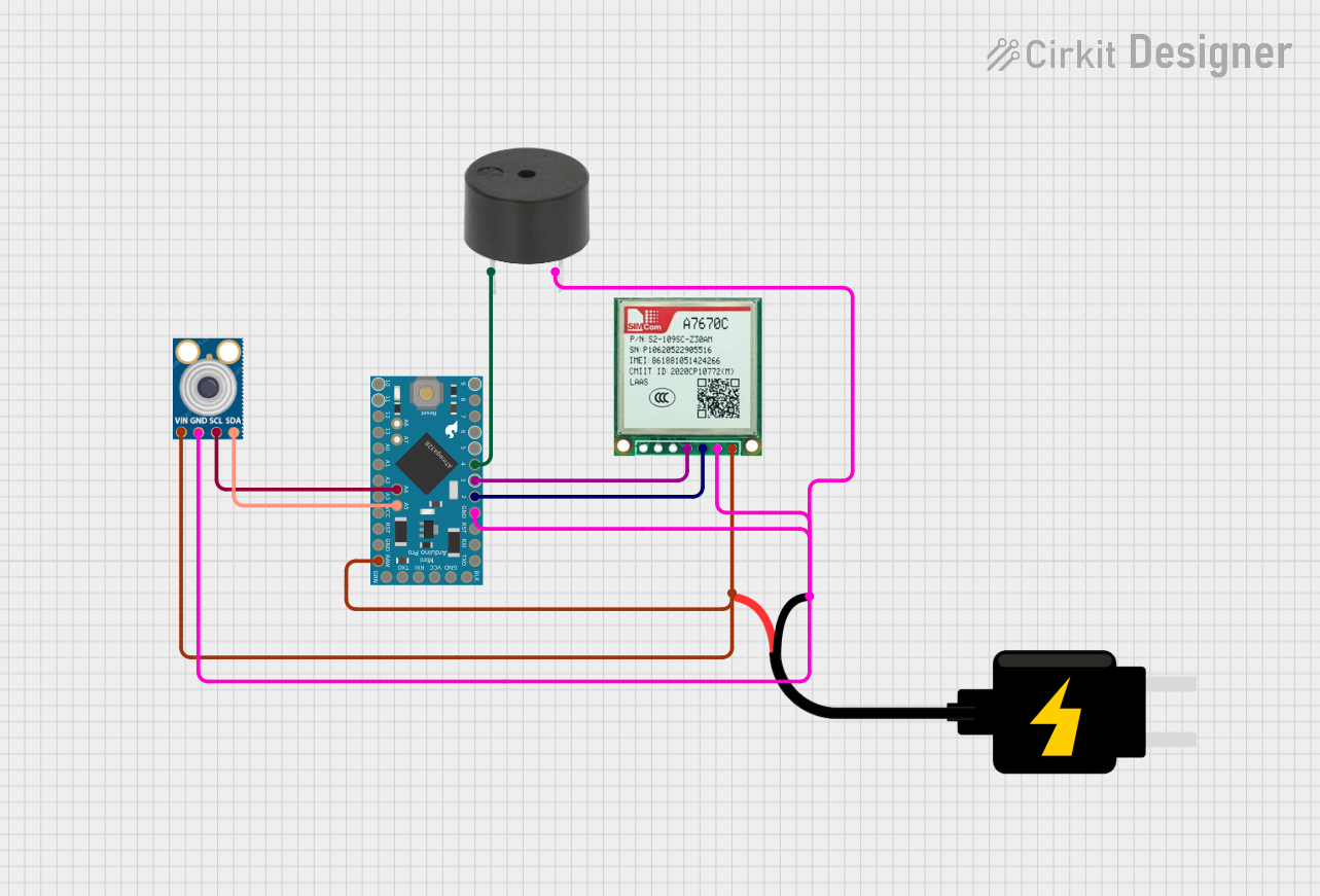

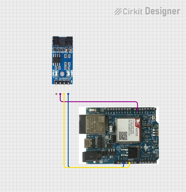
Explore Projects Built with Module Sim a7680c
Common Applications and Use Cases
- Circuit design and optimization in prototyping stages
- Educational tools for teaching electronics and circuit theory
- Research and development for testing new circuit configurations
- Debugging and troubleshooting circuit designs
- Simulation of analog and digital circuits
Technical Specifications
The Module Sim a7680c is equipped with advanced features to support a wide range of simulation needs. Below are its key technical specifications:
General Specifications
| Parameter | Value |
|---|---|
| Manufacturer | Arduino |
| Operating Voltage | 5V DC |
| Power Consumption | 500 mW (typical) |
| Communication Interface | UART, I2C |
| Simulation Modes | Analog, Digital, Mixed-Signal |
| Operating Temperature | -20°C to 70°C |
| Dimensions | 50mm x 30mm x 10mm |
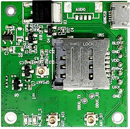
Pin Configuration and Descriptions
The Module Sim a7680c features a simple pinout for easy integration into circuits. Below is the pin configuration:
| Pin Number | Pin Name | Description |
|---|---|---|
| 1 | VCC | Power supply input (5V DC) |
| 2 | GND | Ground connection |
| 3 | TX | UART Transmit pin for communication |
| 4 | RX | UART Receive pin for communication |
| 5 | SDA | I2C Data line |
| 6 | SCL | I2C Clock line |
| 7 | SIM_IN | Input for circuit simulation signals |
| 8 | SIM_OUT | Output for simulated circuit behavior |
Usage Instructions
The Module Sim a7680c is designed for ease of use, making it suitable for both beginners and experienced users. Follow the steps below to integrate and use the module in your projects:
Step 1: Powering the Module
- Connect the VCC pin to a 5V DC power source.
- Connect the GND pin to the ground of your circuit.
Step 2: Communication Setup
- For UART communication:
- Connect the TX pin of the module to the RX pin of your microcontroller.
- Connect the RX pin of the module to the TX pin of your microcontroller.
- For I2C communication:
- Connect the SDA and SCL pins to the corresponding I2C pins on your microcontroller.
Step 3: Simulation Input and Output
- Use the SIM_IN pin to feed the circuit signals you want to simulate.
- Monitor the simulated output on the SIM_OUT pin.
Step 4: Using with Arduino UNO
The Module Sim a7680c can be easily connected to an Arduino UNO for simulation purposes. Below is an example code snippet to get started:
#include <Wire.h> // Include the I2C library for communication

#define SIM_ADDRESS 0x10 // I2C address of the Module Sim a7680c

void setup() {
  Serial.begin(9600); // Initialize UART communication
  Wire.begin();       // Initialize I2C communication

  Serial.println("Module Sim a7680c Initialized");
}

void loop() {
  // Example: Sending a signal to the module via I2C
  Wire.beginTransmission(SIM_ADDRESS);
  Wire.write(0x01); // Send a test signal to the module
  Wire.endTransmission();

  // Example: Reading the simulated output via UART
  if (Serial.available()) {
    int simOutput = Serial.read(); // Read the simulated output
    Serial.print("Simulated Output: ");
    Serial.println(simOutput);
  }

  delay(1000); // Wait for 1 second before the next iteration
}
Important Considerations and Best Practices
- Ensure the module is powered with a stable 5V DC supply to avoid damage.
- Use appropriate pull-up resistors for the I2C lines if not already included in your setup.
- Avoid feeding high-frequency signals directly into the SIM_IN pin without proper filtering.
- Always verify the pin connections before powering the module to prevent short circuits.
Troubleshooting and FAQs
Common Issues and Solutions
The module is not powering on.
- Ensure the VCC and GND pins are properly connected to a 5V DC power source.
- Check for loose connections or damaged wires.
No output on the SIM_OUT pin.
- Verify that a valid signal is being fed into the SIM_IN pin.
- Check the communication interface (UART/I2C) for proper configuration.
Communication failure with Arduino UNO.
- Ensure the correct UART pins (TX/RX) or I2C pins (SDA/SCL) are connected.
- Double-check the baud rate (9600 in the example code) and I2C address (0x10).
Simulated output is incorrect or unstable.
- Verify the input signal parameters and ensure they are within the module's supported range.
- Check for noise or interference in the input signal.
FAQs
Q: Can the Module Sim a7680c simulate both analog and digital circuits?
A: Yes, the module supports analog, digital, and mixed-signal simulation modes.
Q: What is the maximum input signal frequency supported?
A: The module supports input signals up to 1 MHz for accurate simulation.
Q: Is the module compatible with other microcontrollers besides Arduino?
A: Yes, the module can be used with any microcontroller that supports UART or I2C communication.
Q: Does the module require additional software for simulation?
A: No, the module operates independently and does not require additional software. However, you can use Arduino IDE or other tools to interface with it.
By following this documentation, you can effectively integrate and utilize the Module Sim a7680c in your projects. For further assistance, refer to Arduino's official support resources.