How to Use SparkFun_Qwiic_Motor_Driver: Examples, Pinouts, and Specs
Introduction
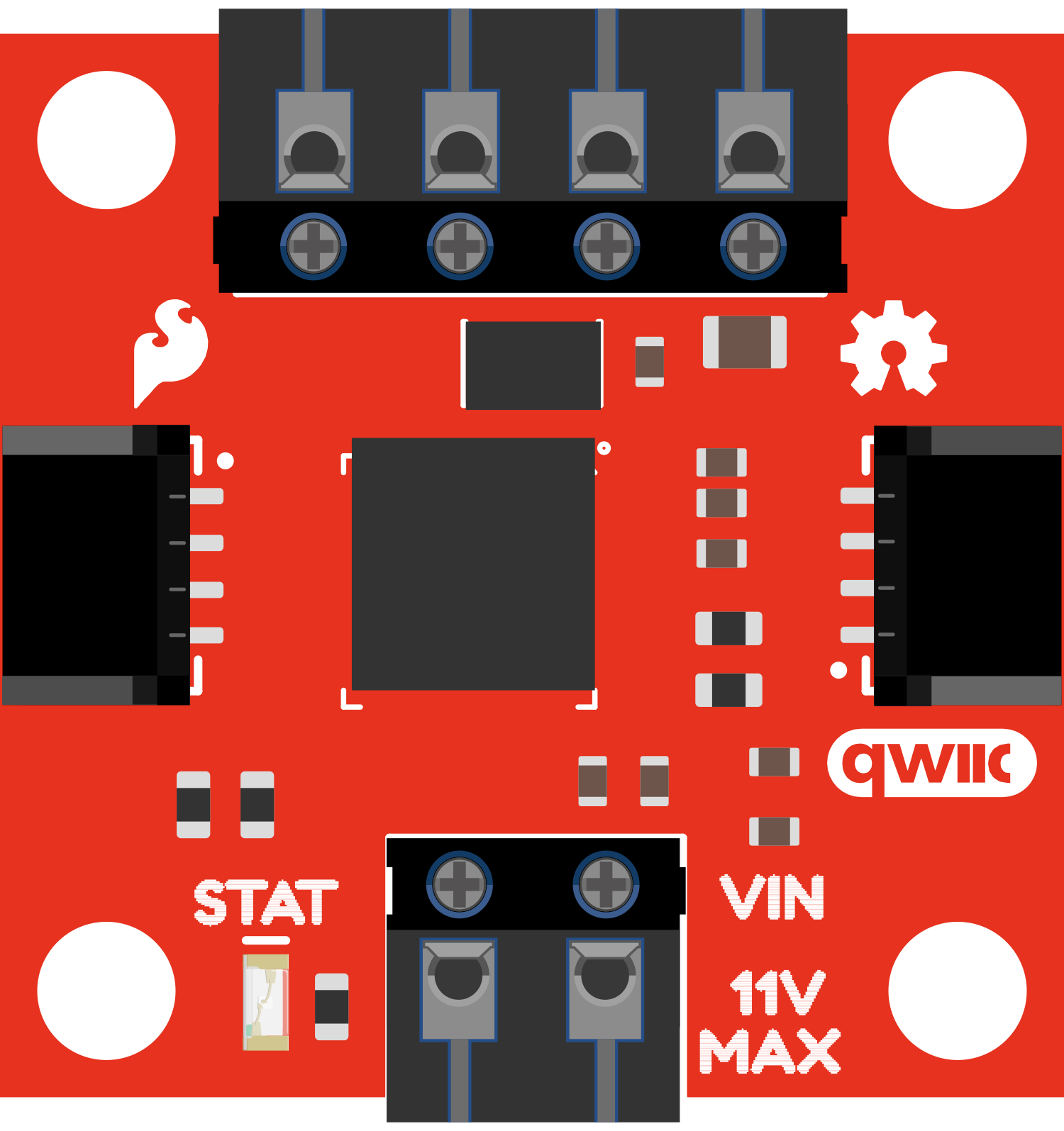
The SparkFun Qwiic Motor Driver is a versatile and user-friendly motor driver breakout board designed to facilitate the control of two brushed DC motors. It is based on the TB6612FNG motor driver chip, which provides efficient and smooth bidirectional control. The board is part of the Qwiic connect system, which allows for easy daisy-chaining and quick prototyping without soldering. Common applications include robotics, custom vehicles, and automation projects.
Explore Projects Built with SparkFun_Qwiic_Motor_Driver
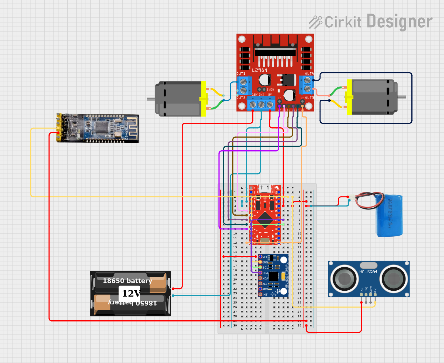
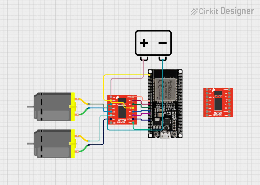
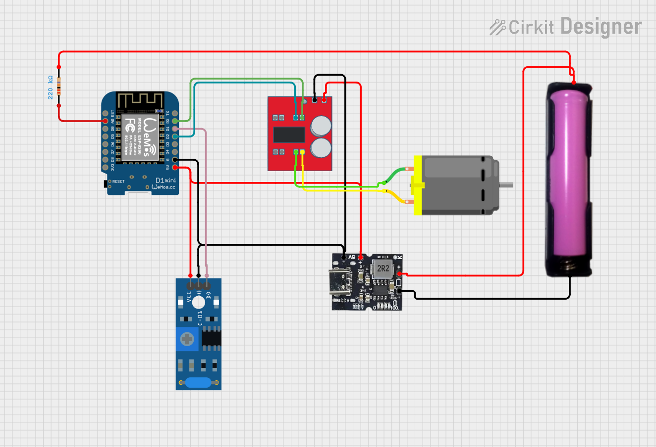
Explore Projects Built with SparkFun_Qwiic_Motor_Driver
Technical Specifications
Key Technical Details
- Motor Driver IC: TB6612FNG
- Motor Channels: 2
- Operating Voltage: 2.5V to 13.5V
- Output Current: Up to 1.2A per channel (3.2A peak)
- Standby Control: To save power
- Logic Voltage: 2.7V to 5.5V (compatible with 3.3V and 5V logic)
- Dimensions: 1.0in x 1.0in (25.4mm x 25.4mm)
Pin Configuration and Descriptions
| Pin Name | Function | Description |
|---|---|---|
GND |
Ground | Reference ground for power and logic. |
VIN |
Voltage In | Motor power supply (2.5V to 13.5V). |
VCC |
Logic Power | Logic power supply (2.7V to 5.5V). |
SDA |
Data Line | I2C data line for Qwiic connection. |
SCL |
Clock Line | I2C clock line for Qwiic connection. |
A1 |
Motor A Terminal 1 | Output to motor A coil 1. |
A2 |
Motor A Terminal 2 | Output to motor A coil 2. |
B1 |
Motor B Terminal 1 | Output to motor B coil 1. |
B2 |
Motor B Terminal 2 | Output to motor B coil 2. |
STBY |
Standby | Controls the standby mode. |
Usage Instructions
Integrating with a Circuit
- Power Connections: Connect
VINto your motor power supply, andVCCto your logic power supply. Ensure thatGNDis connected to the common ground of your system. - Motor Connections: Connect your DC motors to the
A1/A2andB1/B2terminals for motor A and B, respectively. - I2C Connections: Use the Qwiic connectors to link the motor driver to your microcontroller or Qwiic system.
- Standby Mode: Connect
STBYto logic high to enable the motor driver or to logic low to put it in standby mode.
Best Practices
- Always ensure that the power supply does not exceed the recommended voltage range.
- Do not exceed the maximum current rating to prevent damage to the motor driver.
- Use proper decoupling capacitors to minimize voltage spikes.
- Ensure that the
STBYpin is not left floating to avoid unexpected behavior.
Example Code for Arduino UNO
#include <Wire.h> // Include the I2C library (required)

// Define the I2C address for the motor driver (if applicable)
const int motorDriverAddress = 0x58; // Replace with the correct address

void setup() {
  Wire.begin(); // Join the I2C bus as master
  // Initialize the motor driver here (if required)
  // For example, set the standby pin to HIGH
}

void loop() {
  // Code to control the motor speed and direction
  // Example: Set motor A to run at 50% speed forward
  setMotorSpeed(motorDriverAddress, 'A', 128); // 128 out of 255 for 50%
  delay(1000); // Run for 1 second
  // Stop the motor
  setMotorSpeed(motorDriverAddress, 'A', 0);
  delay(1000); // Stop for 1 second
}

// Function to set motor speed and direction
void setMotorSpeed(int address, char motor, int speed) {
  Wire.beginTransmission(address); // Begin transmission to the motor driver
  Wire.write(motor); // Indicate which motor to control
  Wire.write(speed); // Send the speed value
  Wire.endTransmission(); // End transmission
}
Note: The above code is a simplified example. You will need to refer to the SparkFun Qwiic Motor Driver library for specific functions to control the motor driver.
Troubleshooting and FAQs
Common Issues
- Motor not responding: Check connections, ensure power supplies are within the specified range, and verify that the
STBYpin is set to high. - Overcurrent/Overheating: Reduce the load on the motor or improve cooling. Check for shorts or wiring issues.
- Erratic behavior: Ensure that there is no noise on the I2C lines, and that the
STBYpin is not floating.
FAQs
Q: Can I control the speed of the motors? A: Yes, the motor speed can be controlled via PWM signals.
Q: Is the driver compatible with 3.3V systems? A: Yes, the logic voltage range allows for compatibility with both 3.3V and 5V systems.
Q: How do I use the Qwiic connect system? A: The Qwiic system uses I2C for communication. Simply connect the Qwiic connectors to your microcontroller or other Qwiic-enabled devices.
Q: What is the maximum current the driver can handle? A: The driver can handle up to 1.2A per channel continuously, with peaks up to 3.2A.
For further assistance, consult the SparkFun Qwiic Motor Driver datasheet and the TB6612FNG datasheet for in-depth technical information.