How to Use N-MOSFET: Examples, Pinouts, and Specs
Introduction
The N-MOSFET (N-Channel Metal-Oxide-Semiconductor Field-Effect Transistor) is a type of field-effect transistor that uses n-type carriers (electrons) for conduction. It is widely used in electronic circuits for switching and amplifying signals due to its high efficiency, fast switching speed, and low power consumption.
Common applications of N-MOSFETs include:
- Power management in DC-DC converters
- Motor control circuits
- Signal amplification in audio and RF systems
- Digital logic circuits
- Switching in high-speed electronic devices
Explore Projects Built with N-MOSFET

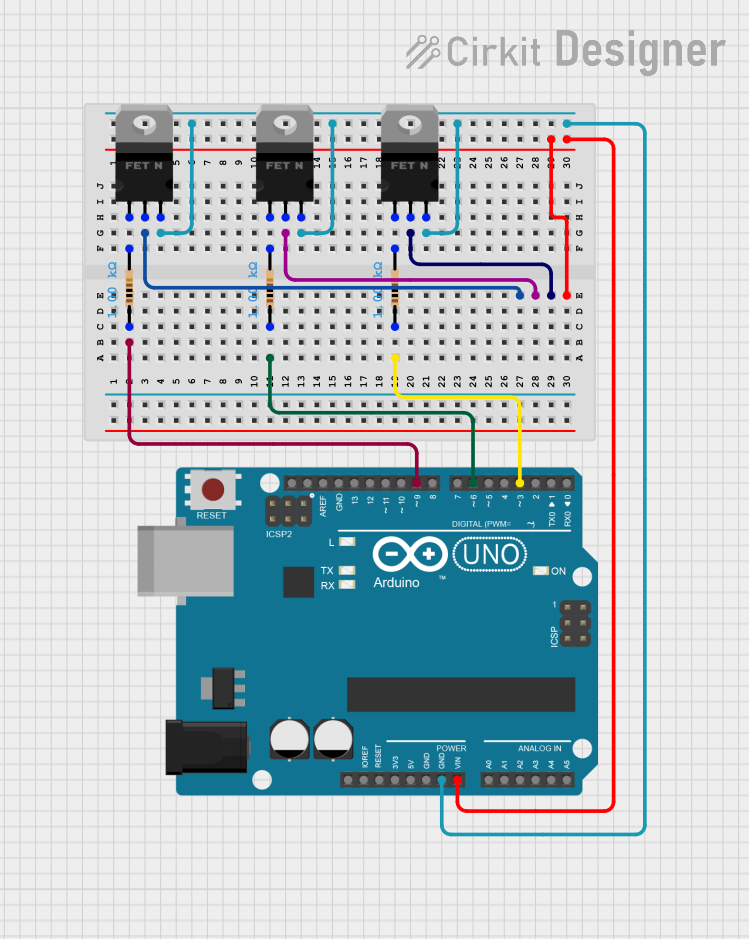

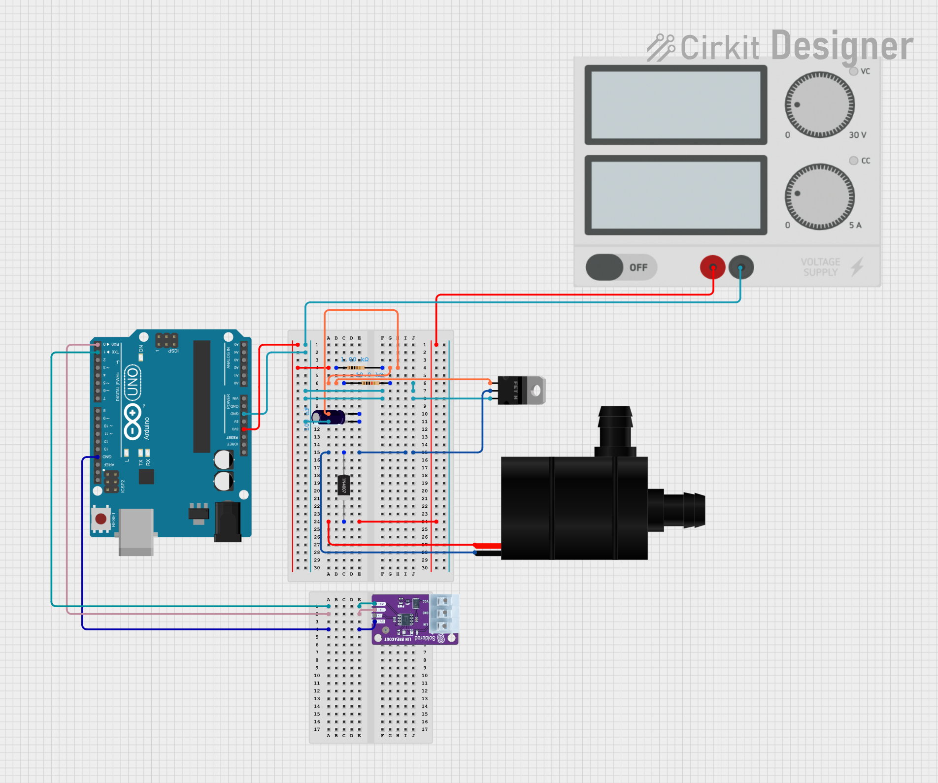
Explore Projects Built with N-MOSFET
Technical Specifications
Below are the general technical specifications for a typical N-MOSFET. Note that specific values may vary depending on the exact model.
| Parameter | Typical Value |
|---|---|
| Drain-Source Voltage (VDS) | 20V to 600V (varies by model) |
| Gate-Source Voltage (VGS) | ±20V |
| Continuous Drain Current (ID) | 1A to 100A (varies by model) |
| Power Dissipation (PD) | 1W to 300W (varies by model) |
| RDS(on) (On-State Resistance) | 0.001Ω to 10Ω (varies by model) |
| Switching Speed | Nanoseconds to microseconds |
| Operating Temperature | -55°C to +150°C |
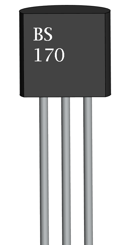
Pin Configuration and Descriptions
The N-MOSFET typically has three pins: Gate (G), Drain (D), and Source (S). Some models may include a fourth pin for the substrate (Body or Bulk), but it is often internally connected to the Source.
| Pin Name | Description |
|---|---|
| Gate (G) | Controls the flow of current between the Drain and Source. |
| Drain (D) | The terminal through which the controlled current flows out of the MOSFET. |
| Source (S) | The terminal through which the current enters the MOSFET. |
| Body (B) | Optional pin; typically connected to the Source internally in most N-MOSFETs. |
Usage Instructions
How to Use the N-MOSFET in a Circuit
- Determine the Operating Voltage and Current: Ensure the N-MOSFET's voltage and current ratings are suitable for your application.
- Connect the Gate: Use a resistor (typically 10Ω to 1kΩ) between the Gate and the control signal to limit inrush current and prevent damage.
- Connect the Drain and Source: The Drain is connected to the load, and the Source is connected to ground (for low-side switching).
- Apply Gate Voltage: To turn the N-MOSFET on, apply a voltage (VGS) higher than the threshold voltage (Vth). For most logic-level N-MOSFETs, this is typically 5V or higher.
Important Considerations and Best Practices
- Gate Drive Voltage: Ensure the Gate voltage is sufficient to fully turn on the MOSFET (VGS > Vth).
- Heat Dissipation: Use a heatsink or proper thermal management for high-power applications.
- Flyback Diode: When switching inductive loads (e.g., motors), include a flyback diode across the load to protect the MOSFET from voltage spikes.
- Avoid Overvoltage: Do not exceed the maximum VDS or VGS ratings to prevent damage.
Example: Using an N-MOSFET with Arduino UNO
Below is an example of using an N-MOSFET to control an LED with an Arduino UNO.
// Example: Controlling an LED with an N-MOSFET and Arduino UNO
// Connect the MOSFET's Gate to pin 9 of the Arduino through a 220Ω resistor.
// The Source is connected to ground, and the Drain is connected to the LED's cathode.
// The LED's anode is connected to a 5V power supply through a 330Ω resistor.

const int mosfetGatePin = 9; // Pin connected to the MOSFET Gate

void setup() {
  pinMode(mosfetGatePin, OUTPUT); // Set the MOSFET Gate pin as an output
}

void loop() {
  digitalWrite(mosfetGatePin, HIGH); // Turn the MOSFET on (LED lights up)
  delay(1000);                       // Wait for 1 second
  digitalWrite(mosfetGatePin, LOW);  // Turn the MOSFET off (LED turns off)
  delay(1000);                       // Wait for 1 second
}
Troubleshooting and FAQs
Common Issues and Solutions
MOSFET Not Turning On
- Cause: Insufficient Gate voltage (VGS).
- Solution: Ensure the Gate voltage exceeds the threshold voltage (Vth). For logic-level MOSFETs, use a 5V or 3.3V control signal.
Excessive Heat Generation
- Cause: High current or insufficient cooling.
- Solution: Use a heatsink or select a MOSFET with a lower RDS(on) value.
MOSFET Fails or Shorts
- Cause: Overvoltage or voltage spikes.
- Solution: Add a flyback diode for inductive loads and ensure voltage ratings are not exceeded.
Slow Switching
- Cause: High Gate capacitance or insufficient drive current.
- Solution: Use a Gate driver circuit to provide sufficient current for fast switching.
FAQs
Q: Can I use an N-MOSFET for high-side switching?
A: Yes, but you will need a Gate driver circuit to provide a voltage higher than the supply voltage to the Gate.
Q: What is the difference between an N-MOSFET and a P-MOSFET?
A: An N-MOSFET uses electrons (n-type carriers) for conduction, while a P-MOSFET uses holes (p-type carriers). N-MOSFETs typically have lower RDS(on) and faster switching speeds.
Q: How do I choose the right N-MOSFET for my application?
A: Consider the voltage and current ratings, RDS(on), switching speed, and thermal performance based on your circuit requirements.