How to Use 36V 350W Hub Motor: Examples, Pinouts, and Specs
Introduction
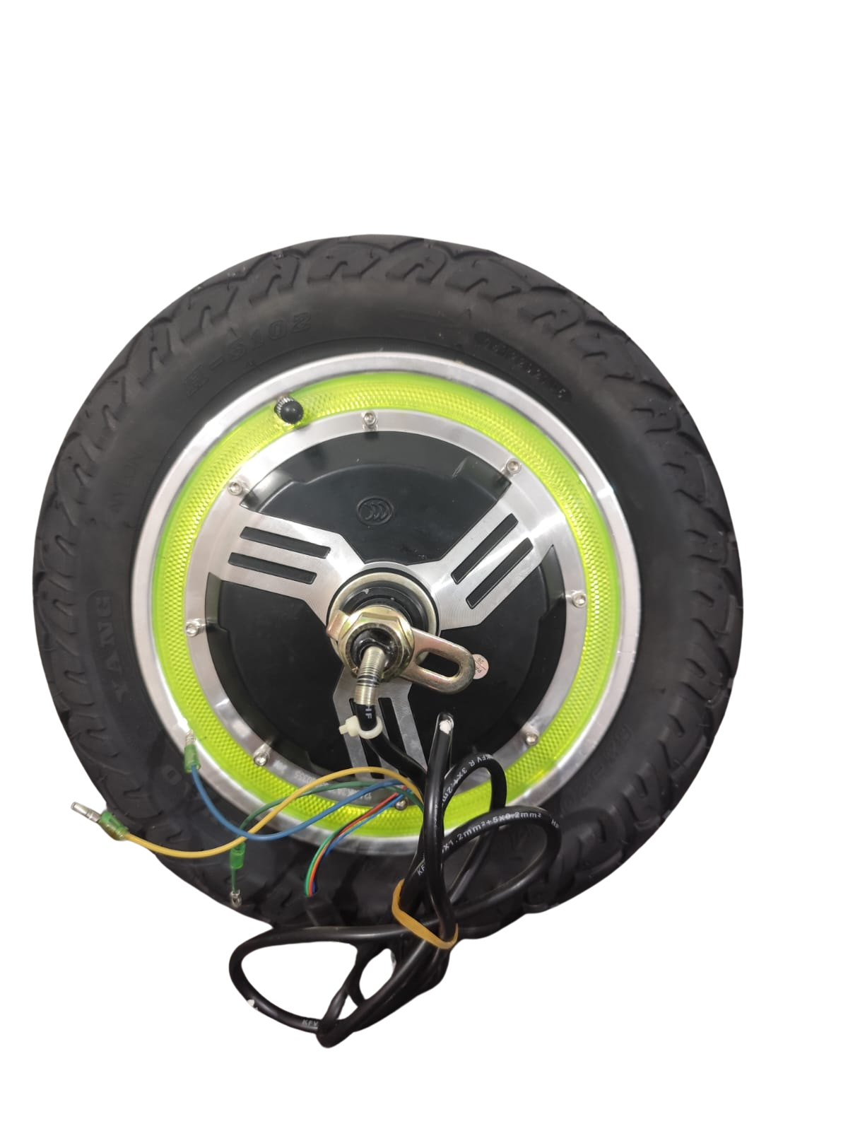
The 36V 350W Hub Motor is a high-performance motor designed for electric bicycles and scooters. It is integrated directly into the wheel hub, eliminating the need for external drive systems such as chains or belts. This compact and efficient design provides smooth propulsion, making it an ideal choice for personal electric vehicles. With a power output of 350 watts and an operating voltage of 36 volts, this motor delivers reliable performance for urban commuting and recreational use.
Explore Projects Built with 36V 350W Hub Motor


Explore Projects Built with 36V 350W Hub Motor
Common Applications and Use Cases
- Electric bicycles (e-bikes)
- Electric scooters
- Lightweight electric vehicles
- DIY electric mobility projects
- Last-mile transportation solutions
Technical Specifications
Key Technical Details
| Parameter | Value |
|---|---|
| Rated Voltage | 36V |
| Rated Power | 350W |
| Motor Type | Brushless DC (BLDC) |
| Maximum Speed | ~25-30 km/h (varies by wheel size) |
| Torque | ~30-40 Nm (approximate) |
| Efficiency | ≥80% |
| Wheel Compatibility | 20" to 28" wheels |
| Weight | ~3-4 kg |
| Operating Temperature | -20°C to 45°C |
| Waterproof Rating | IP54 (splash-resistant) |
Pin Configuration and Descriptions
The hub motor typically comes with a multi-pin connector for interfacing with the motor controller. Below is a description of the common pin configuration:
| Pin Number | Wire Color | Function |
|---|---|---|
| 1 | Yellow | Phase A (Motor Coil) |
| 2 | Green | Phase B (Motor Coil) |
| 3 | Blue | Phase C (Motor Coil) |
| 4 | Red | Hall Sensor Power (+5V) |
| 5 | Black | Hall Sensor Ground (GND) |
| 6 | Yellow | Hall Sensor A Signal |
| 7 | Green | Hall Sensor B Signal |
| 8 | Blue | Hall Sensor C Signal |
| 9 | Thick Red | Battery Positive (+36V) |
| 10 | Thick Black | Battery Negative (GND) |
Note: The exact pinout may vary depending on the manufacturer. Always refer to the datasheet or manual provided with your motor.
Usage Instructions
How to Use the Component in a Circuit
Connect the Motor to a Controller:
- Use a compatible motor controller designed for 36V BLDC motors.
- Connect the phase wires (Yellow, Green, Blue) from the motor to the corresponding phase outputs on the controller.
- Connect the Hall sensor wires (Red, Black, Yellow, Green, Blue) to the controller's Hall sensor inputs.
Power the System:
- Connect a 36V battery to the motor controller's power input terminals (positive and negative).
- Ensure the battery capacity is sufficient to handle the motor's power requirements (e.g., 10Ah or higher).
Throttle and Braking:
- Attach a throttle to the controller's throttle input for speed control.
- If applicable, connect an electronic brake or regenerative braking system.
Mounting:
- Install the hub motor into the wheel of your bicycle or scooter.
- Secure the axle properly to prevent movement during operation.
Testing:
- Power on the system and test the motor at low speeds to ensure proper operation.
- Gradually increase speed and check for smooth performance.
Important Considerations and Best Practices
- Battery Compatibility: Ensure the battery voltage matches the motor's rated voltage (36V).
- Controller Selection: Use a motor controller that supports 36V 350W BLDC motors and has appropriate current limits.
- Heat Management: Avoid prolonged operation at maximum load to prevent overheating.
- Waterproofing: While the motor is splash-resistant (IP54), avoid submerging it in water.
- Wheel Size: The motor's performance (speed and torque) depends on the wheel size. Larger wheels may reduce torque but increase top speed.
Arduino Integration Example
While the hub motor is typically controlled using a dedicated motor controller, you can use an Arduino to send control signals to the controller. Below is an example of controlling the motor speed using a PWM signal:
// Example: Controlling motor speed using Arduino PWM
// Connect the Arduino PWM pin to the motor controller's throttle input

const int throttlePin = 9; // PWM pin connected to motor controller throttle

void setup() {
  pinMode(throttlePin, OUTPUT); // Set throttle pin as output
}

void loop() {
  // Gradually increase motor speed
  for (int speed = 0; speed <= 255; speed++) {
    analogWrite(throttlePin, speed); // Send PWM signal (0-255)
    delay(20); // Wait 20ms before increasing speed
  }

  // Gradually decrease motor speed
  for (int speed = 255; speed >= 0; speed--) {
    analogWrite(throttlePin, speed); // Send PWM signal (0-255)
    delay(20); // Wait 20ms before decreasing speed
  }
}
Note: Ensure the motor controller supports PWM input for throttle control. Consult the controller's documentation for specific requirements.
Troubleshooting and FAQs
Common Issues and Solutions
Motor Does Not Spin:
- Cause: Incorrect wiring or loose connections.
- Solution: Double-check all connections, especially phase and Hall sensor wires.
Jerky or Noisy Operation:
- Cause: Incorrect phase wiring or damaged Hall sensors.
- Solution: Verify the phase wire order and test the Hall sensors for proper operation.
Overheating:
- Cause: Prolonged operation at high load or insufficient cooling.
- Solution: Reduce load, ensure proper ventilation, and avoid overloading the motor.
Low Speed or Torque:
- Cause: Incompatible wheel size or low battery voltage.
- Solution: Use a wheel size appropriate for the motor and ensure the battery is fully charged.
FAQs
Q: Can I use a 48V battery with this motor?
A: No, the motor is designed for 36V operation. Using a higher voltage may damage the motor or controller.
Q: Is the motor suitable for off-road use?
A: The motor is primarily designed for urban and light off-road use. For rugged terrain, consider a motor with higher torque and a better waterproof rating.
Q: How do I determine the correct wheel size?
A: The motor is compatible with 20" to 28" wheels. Choose a size based on your desired speed and torque balance.
Q: Can I use regenerative braking with this motor?
A: Yes, if your motor controller supports regenerative braking, it can be used with this motor. Check the controller's specifications for compatibility.