Cirkit Designer Logo
Cirkit Designer
Your all-in-one circuit design IDE
Home / 
Component Documentation

How to Use Gravity 1-8 I2C Multiplexer: Examples, Pinouts, and Specs

Image of Gravity 1-8 I2C Multiplexer
Cirkit Designer LogoDesign with Gravity 1-8 I2C Multiplexer in Cirkit Designer

Introduction

The Gravity 1-8 I2C Multiplexer by DFRobot is a versatile module designed to expand the capabilities of a single I2C bus. It allows up to eight I2C devices to be connected simultaneously, even if they share the same I2C address. By dynamically switching between different channels, this multiplexer eliminates address conflicts and simplifies the integration of multiple I2C devices in a single project.

Explore Projects Built with Gravity 1-8 I2C Multiplexer

Use Cirkit Designer to design, explore, and prototype these projects online. Some projects support real-time simulation. Click "Open Project" to start designing instantly!
Wi-Fi Enabled Sensor Hub with ESP8266 and ADS1115 ADC
Image of Node Mcu Gas Sensor: A project utilizing Gravity 1-8 I2C Multiplexer in a practical application
This circuit features two ESP8266 NodeMCU microcontrollers, each interfaced with a Gravity I2C ADS1115 16-Bit ADC module for analog-to-digital conversion. The microcontrollers communicate with the ADC modules via I2C protocol, with one set of connections for each microcontroller-ADC pair, and are powered through a common 3.3V and ground connection.
Cirkit Designer LogoOpen Project in Cirkit Designer
ESP32 and MCP23017-Based Smart Relay Control System with DHT22 Sensors
Image of Indoor Lounge: A project utilizing Gravity 1-8 I2C Multiplexer in a practical application
This circuit is a control system that uses an ESP32 microcontroller to manage multiple relays and read data from DHT22 temperature and humidity sensors. The DFRobot Gravity MCP23017 I2C module expands the GPIO capabilities of the ESP32, allowing it to control additional relays for switching high-power devices.
Cirkit Designer LogoOpen Project in Cirkit Designer
Arduino UNO with MPU-6050 Sensor Array and Multiplexer Control Circuit
Image of smrpe: A project utilizing Gravity 1-8 I2C Multiplexer in a practical application
This circuit is designed to interface multiple MPU-6050 sensors with an Arduino UNO for motion tracking purposes. The HCF4052BE analog multiplexer/demultiplexer is used to switch between the MPU-6050 sensors' SCL and SDA lines, allowing for multiple sensors to share the same I2C bus. The Arduino runs embedded code to read capacitive touch inputs, accelerometer and gyroscope data from the MPU-6050 sensors, and transmit this information via Bluetooth and Wi-Fi using software serial communication.
Cirkit Designer LogoOpen Project in Cirkit Designer
ESP32-Based Multi-Sensor Data Logger with MPU-6050 and I2C Multiplexing
Image of project_final: A project utilizing Gravity 1-8 I2C Multiplexer in a practical application
This circuit features an ESP32 Devkit V1 microcontroller connected to four MPU-6050 sensors via an Adafruit TCA9548A I2C multiplexer. The ESP32 facilitates communication with each MPU-6050 sensor, which are likely used for motion tracking due to their integrated gyroscope and accelerometer. The multiplexer allows the ESP32 to interface with multiple sensors that share the same I2C address by providing separate I2C channels for each sensor.
Cirkit Designer LogoOpen Project in Cirkit Designer

Explore Projects Built with Gravity 1-8 I2C Multiplexer

Use Cirkit Designer to design, explore, and prototype these projects online. Some projects support real-time simulation. Click "Open Project" to start designing instantly!
Image of Node Mcu Gas Sensor: A project utilizing Gravity 1-8 I2C Multiplexer in a practical application
Wi-Fi Enabled Sensor Hub with ESP8266 and ADS1115 ADC
This circuit features two ESP8266 NodeMCU microcontrollers, each interfaced with a Gravity I2C ADS1115 16-Bit ADC module for analog-to-digital conversion. The microcontrollers communicate with the ADC modules via I2C protocol, with one set of connections for each microcontroller-ADC pair, and are powered through a common 3.3V and ground connection.
Cirkit Designer LogoOpen Project in Cirkit Designer
Image of Indoor Lounge: A project utilizing Gravity 1-8 I2C Multiplexer in a practical application
ESP32 and MCP23017-Based Smart Relay Control System with DHT22 Sensors
This circuit is a control system that uses an ESP32 microcontroller to manage multiple relays and read data from DHT22 temperature and humidity sensors. The DFRobot Gravity MCP23017 I2C module expands the GPIO capabilities of the ESP32, allowing it to control additional relays for switching high-power devices.
Cirkit Designer LogoOpen Project in Cirkit Designer
Image of smrpe: A project utilizing Gravity 1-8 I2C Multiplexer in a practical application
Arduino UNO with MPU-6050 Sensor Array and Multiplexer Control Circuit
This circuit is designed to interface multiple MPU-6050 sensors with an Arduino UNO for motion tracking purposes. The HCF4052BE analog multiplexer/demultiplexer is used to switch between the MPU-6050 sensors' SCL and SDA lines, allowing for multiple sensors to share the same I2C bus. The Arduino runs embedded code to read capacitive touch inputs, accelerometer and gyroscope data from the MPU-6050 sensors, and transmit this information via Bluetooth and Wi-Fi using software serial communication.
Cirkit Designer LogoOpen Project in Cirkit Designer
Image of project_final: A project utilizing Gravity 1-8 I2C Multiplexer in a practical application
ESP32-Based Multi-Sensor Data Logger with MPU-6050 and I2C Multiplexing
This circuit features an ESP32 Devkit V1 microcontroller connected to four MPU-6050 sensors via an Adafruit TCA9548A I2C multiplexer. The ESP32 facilitates communication with each MPU-6050 sensor, which are likely used for motion tracking due to their integrated gyroscope and accelerometer. The multiplexer allows the ESP32 to interface with multiple sensors that share the same I2C address by providing separate I2C channels for each sensor.
Cirkit Designer LogoOpen Project in Cirkit Designer

Common Applications and Use Cases

  • Connecting multiple sensors or modules with identical I2C addresses.
  • Expanding the I2C bus for complex projects with numerous peripherals.
  • Prototyping and testing multiple I2C devices in parallel.
  • Robotics, IoT, and automation systems requiring multiple I2C devices.

Technical Specifications

Below are the key technical details of the Gravity 1-8 I2C Multiplexer:

Parameter Specification
Operating Voltage 3.3V to 5V
Communication Protocol I2C
Default I2C Address 0x70 (modifiable via solder pads)
Number of Channels 8
Maximum I2C Speed 400 kHz
Dimensions 42mm x 32mm
Mounting Holes 3mm diameter

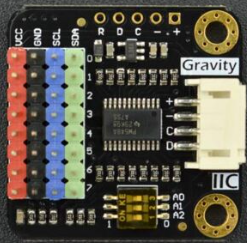
Pin Configuration and Descriptions

The Gravity 1-8 I2C Multiplexer features the following pin layout:

Pin Name Description
VIN Power input (3.3V to 5V).
GND Ground connection.
SDA I2C data line (connect to the master device's SDA).
SCL I2C clock line (connect to the master device's SCL).
CH0-CH7 Eight I2C channels for connecting devices. Each channel has its own SDA and SCL.

Usage Instructions

How to Use the Component in a Circuit

  1. Power the Multiplexer: Connect the VIN pin to a 3.3V or 5V power source and the GND pin to ground.
  2. Connect the I2C Bus: Attach the SDA and SCL pins of the multiplexer to the corresponding SDA and SCL pins of your microcontroller or master device.
  3. Connect I2C Devices: Attach up to eight I2C devices to the CH0-CH7 channels. Each channel has its own SDA and SCL pins.
  4. Select a Channel: Use I2C commands to select the desired channel for communication. Only one channel can be active at a time.

Important Considerations and Best Practices

  • Avoid Address Conflicts: The multiplexer is specifically designed to handle devices with identical I2C addresses. Ensure that devices connected to different channels do not share the same address on the same channel.
  • I2C Address Configuration: The default I2C address of the multiplexer is 0x70. If multiple multiplexers are used, modify their addresses by adjusting the solder pads on the board.
  • Pull-Up Resistors: The module includes onboard pull-up resistors for the I2C bus. If additional pull-up resistors are present in your circuit, ensure the total resistance is within acceptable limits to avoid signal integrity issues.

Example Code for Arduino UNO

Below is an example of how to use the Gravity 1-8 I2C Multiplexer with an Arduino UNO:

#include <Wire.h>

// Define the I2C address of the multiplexer
#define TCA9548A_ADDR 0x70

// Function to select a specific channel on the multiplexer
void selectChannel(uint8_t channel) {
  if (channel > 7) return; // Ensure the channel is within range (0-7)
  Wire.beginTransmission(TCA9548A_ADDR);
  Wire.write(1 << channel); // Activate the desired channel
  Wire.endTransmission();
}

void setup() {
  Wire.begin(); // Initialize I2C communication
  Serial.begin(9600); // Start serial communication for debugging

  Serial.println("Initializing I2C Multiplexer...");
  selectChannel(0); // Select channel 0 as an example
}

void loop() {
  // Example: Communicate with a device on channel 0
  selectChannel(0); // Ensure channel 0 is active
  Wire.beginTransmission(0x40); // Replace 0x40 with the I2C address of your device
  Wire.write(0x00); // Example command to the device
  Wire.endTransmission();

  delay(1000); // Wait for 1 second before repeating
}

Troubleshooting and FAQs

Common Issues and Solutions

  1. I2C Devices Not Responding:

    • Ensure the correct channel is selected using the selectChannel() function.
    • Verify that the I2C address of the device is correct.
    • Check the wiring and ensure proper connections to the SDA and SCL pins.
  2. Address Conflicts Persist:

    • Confirm that devices with identical addresses are connected to different channels.
    • If using multiple multiplexers, ensure each has a unique I2C address.
  3. Communication Errors at High Speeds:

    • Reduce the I2C clock speed if communication errors occur at 400 kHz.
    • Check for excessive capacitance on the I2C lines, which can degrade signal quality.

FAQs

Q: Can I use more than one multiplexer in a single project?
A: Yes, you can use multiple multiplexers by assigning each a unique I2C address. Modify the solder pads on the board to change the address.

Q: Do I need to deactivate a channel after use?
A: No, the multiplexer automatically deactivates other channels when a new channel is selected.

Q: Can I connect devices with different voltage levels?
A: No, all devices connected to the multiplexer must operate at the same voltage level as the multiplexer (3.3V or 5V). Use level shifters if necessary.

Q: How do I check if the multiplexer is working?
A: Use an I2C scanner sketch to detect the multiplexer at its default address (0x70). If detected, the multiplexer is functioning correctly.